Manual cutting · chemical aeration
7 equipment items
CLC PHYSICAL-FOAMING LINE
Delivery lead time: 40–50 working days.
PROCESS ROUTEPhysical foaming · Non-autoclaved curing
CLC / foam concrete block production using physical foaming and non-autoclaved curing. Explore the line visual, production stages, equipment configuration, project examples and installation support.
Get a Production Line Proposal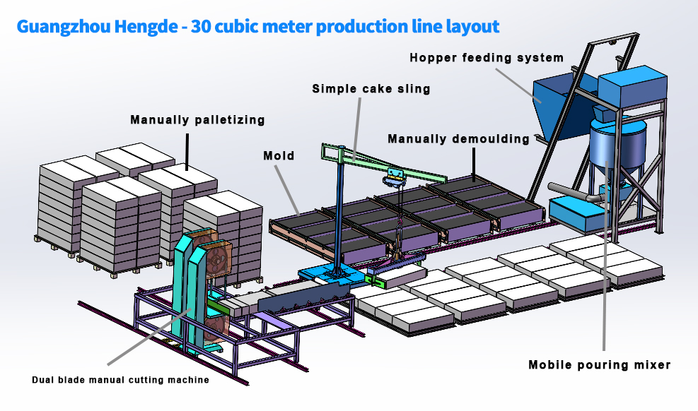 Open full-size layout
CAPACITY QUICK INFORMATION
CAPACITY & EQUIPMENT CONFIGURATION
AVAILABLE CONFIGURATIONS
Compare equipment configurations for the same planned capacity. The table below shows the primary configuration; our engineers select the applicable route after reviewing your product and raw materials.
7 equipment items
8 equipment items
6 equipment items
SIX-STEP PROCESS
Meter powder, aggregate and water to the batch formulation.
Generate preformed foam and control its addition to the metered slurry for the target fresh density.
Fill the mould configuration selected for the block product and production capacity.
Match the non-autoclaved curing time, mould count and demoulding condition to the product.
Match billet condition, cutting sequence and transfer speed to the cutting system in this configuration.
Connect block transfer and stacking to the cutting cycle and finished-product storage area.
COMPLETE EQUIPMENT CONFIGURATION
Review the equipment for each production stage. Select an equipment image to enlarge it, or open a linked equipment name for more detail.
| No. | Equipment | Stage | Model | Dimensions | Qty. | Unit power | Total power (kW) |
|---|---|---|---|---|---|---|---|
| Preparation & metering | |||||||
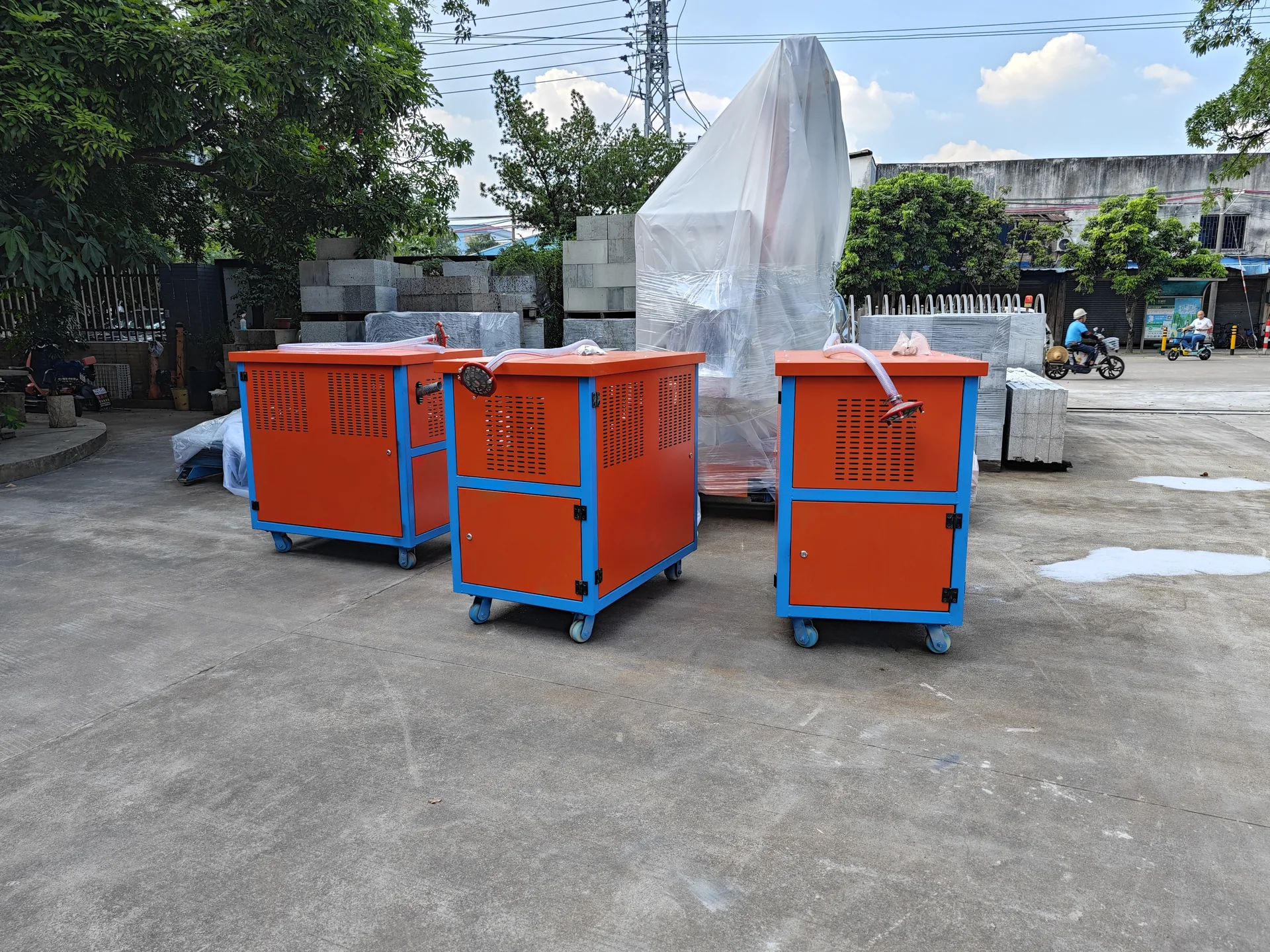
| 1 | 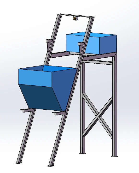 Measuring system | Preparation & metering | HLY-04-00 | 3.65 m × 1.35 m × 4.2 m | 1 | 0.55 kW | 0.55 kW |
| Physical foaming & mixing | |||||||
| 2 | Physical foaming machine | Physical foaming & mixing | EPSA-1 | 2000 × 1200 × 1200 | 1 | 11 kW | 11 kW |
| 3 | Physical foaming & mixing | HDKWF1-001 | 1150 × 750 × 1140 | 1 | 7.5 kW | 7.5 kW | |
| Cutting & finishing | |||||||
| 4 | 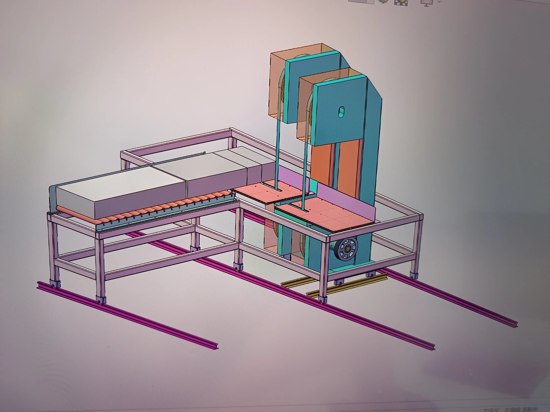 Vertical push cutter | Cutting & finishing | HLY-00 | 2.0 m × 1.35 m × 1.85 m | 1 | 7.5 kW | 7.5 kW |
| Handling & stacking | |||||||
| 5 | 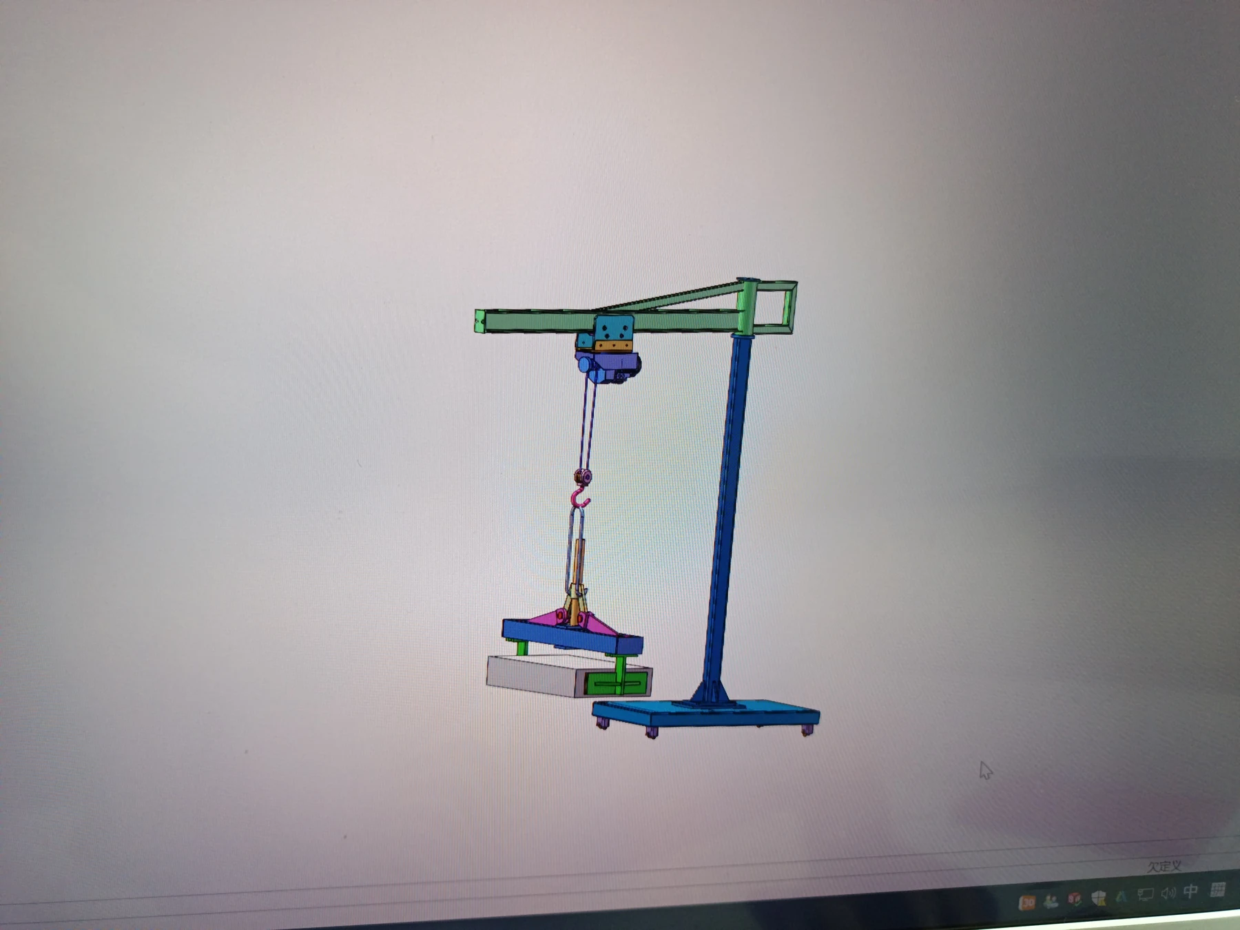 Manual cantilever billet lifter | Handling & stacking | HLY-03-00 | 3.0 m × 1.3 × 3.2 m | 1 | — | — |
| Moulding, curing & circulation | |||||||
| 6 | 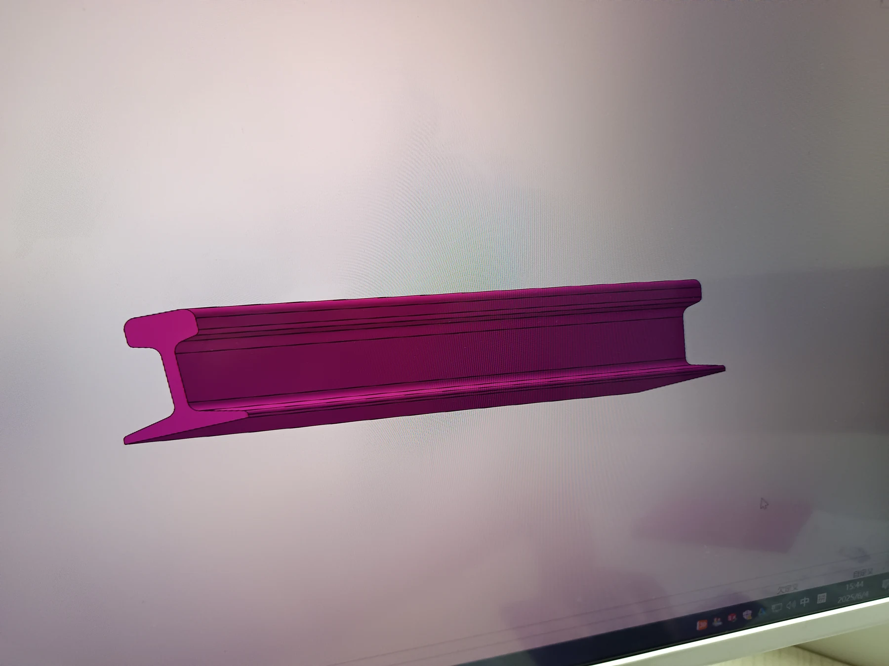 Pourer track line | Moulding, curing & circulation | HLY-07 | 6 m | 2 | — | — |
| 7 | Cantilever lifter track line | Moulding, curing & circulation | HLY-08 | 3.5M | 2 | — | — |
| PLC, electrical & tooling | |||||||
| 8 | 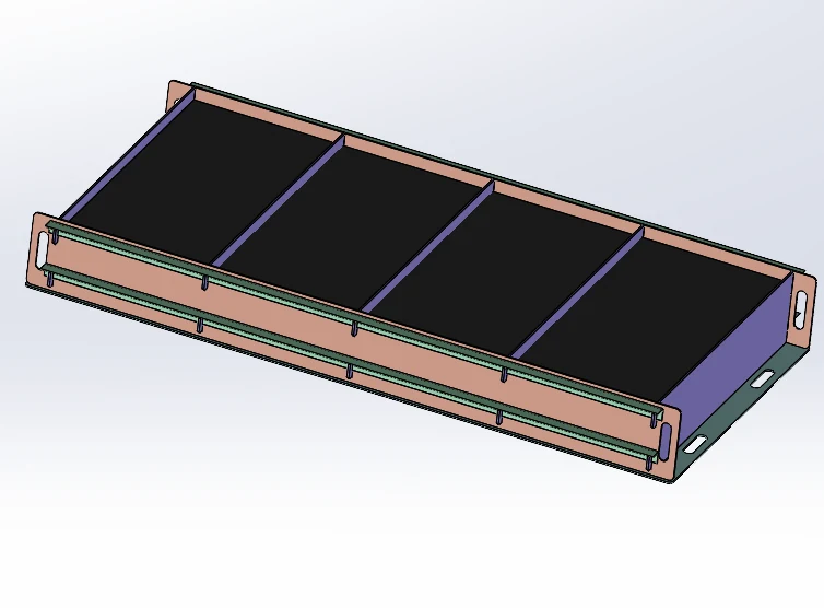 Spliced mould | Production equipment | JMX-01-01ZT | 2.6 m × 1.3 m × 0.3 m | 20 | — | — |
PRODUCTION LINE GALLERY
Drag or swipe through real equipment photos and engineering layouts. Open the main image to inspect it at full size.
PROJECT DELIVERY / TURNKEY SUPPORT
HENGDE connects raw-material testing, factory planning, equipment manufacturing and site commissioning in one delivery plan. Our engineers develop the production route and machine interfaces, and our team prepares operators for production and maintenance. The proposal identifies the equipment, site preparation and services for your factory.
Evaluate representative samples from the project location before selecting the final process.
Adjust the formulation and material ratios against the test results and target product.
Confirm product dimensions and the product-specific preparation, forming, curing and finishing process.
Coordinate land, buildings, storage, material flow, foundations and utilities.
Match capacity, automation, budget, moulds and process interfaces to the agreed factory scope.
Prepare the agreed machines, tooling and controls against the approved configuration.
Check applicable equipment and delivery scope before shipment.
Coordinate packing, loading and destination requirements with the project shipping plan.
Install and connect the agreed equipment after site conditions are ready.
Check machine sequences and trial production with the selected materials.
Train operators in safe use, production sequence and routine maintenance.
Plan maintenance communication and spare-parts support for the installed equipment.
REAL HENGDE PROJECTS
HENGDE projects selected by product family, process route, capacity and current delivery stage.
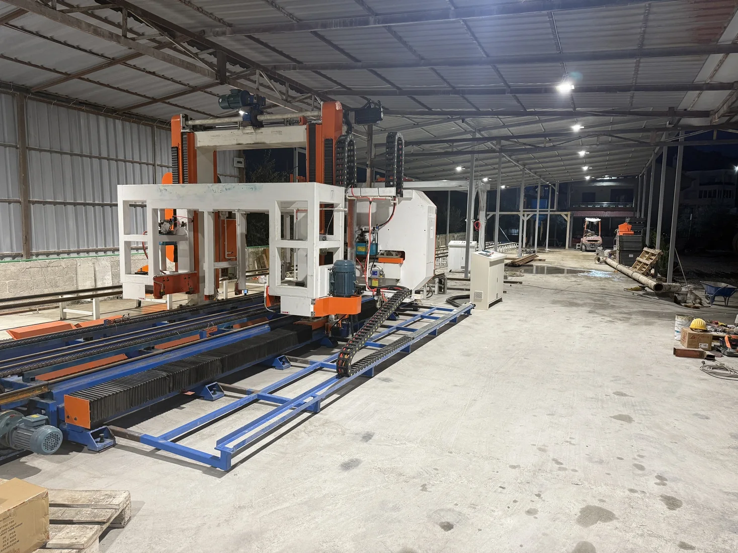 Tirana, Albania
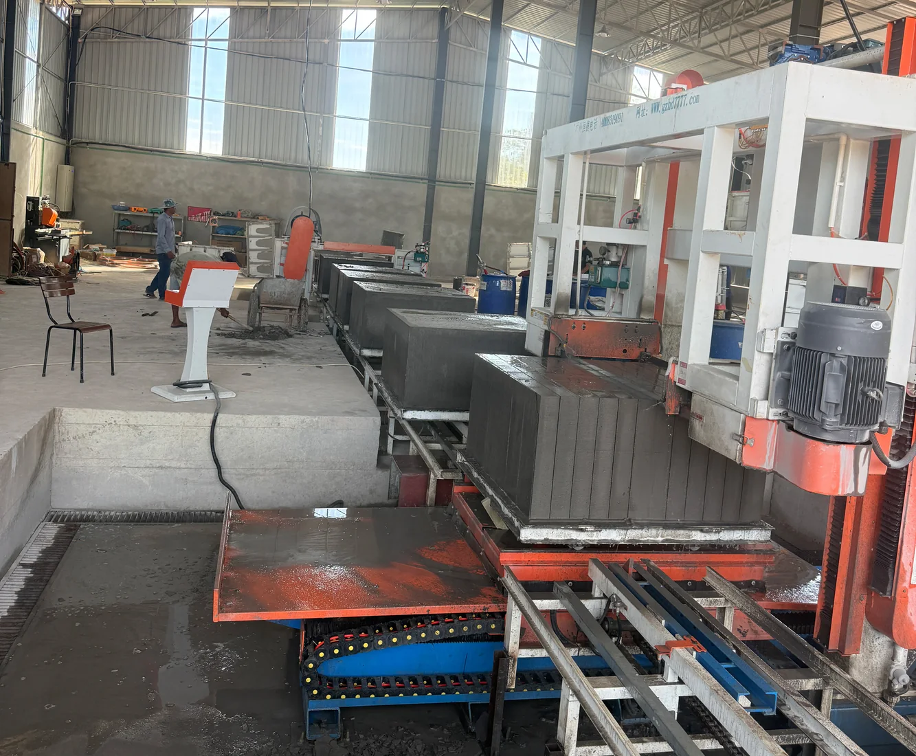 Phnom Penh, Cambodia
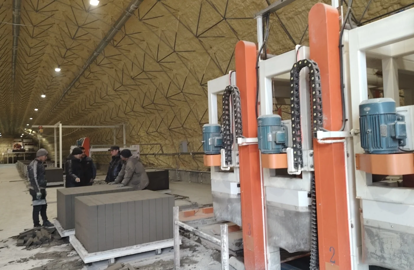 Bishkek, Kyrgyzstan
HENGDE develops the CLC formulation from your local binder, mineral inputs and process water, then matches foam generation, batching and mixing to this capacity configuration.
HENGDE checks binder and mineral composition, particle grading, moisture and water quality against your block density and strength targets.
For recycled inputs, we define sorting and preparation needs and use representative samples to establish a workable formulation.
Our engineers adjust slurry proportions, water ratio, foam dosage and addition sequence, then check fresh density and mould filling in the trials.
We connect setting and cutting observations to the mould-turnover plan, curing space and downstream handling cycle.
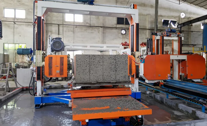
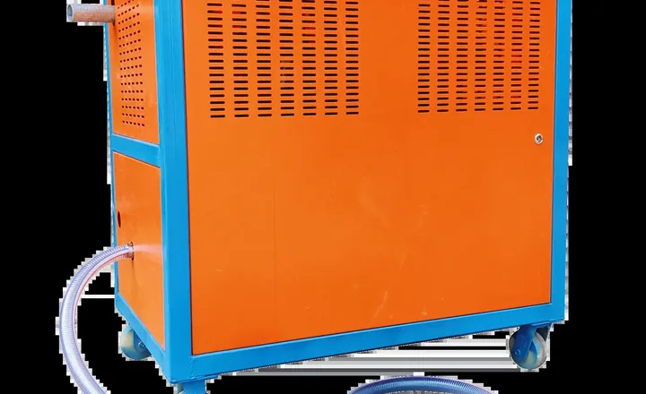
HENGDE plans collection, drainage and settling as a connected recovery loop. We size the recovery area and select pump and return-water arrangements around the cutting process, factory layout and material-test results.
Send HENGDE the material sources, available test reports and product you want to manufacture. Our team will define the assessment and trial steps for your production route.
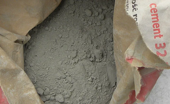
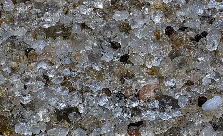
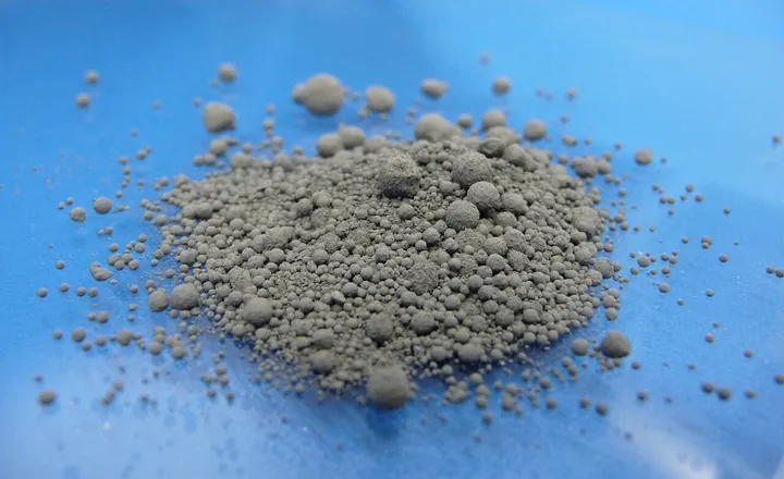
Representative material photographs: cement, Szlomo Lejb / Sumek101; river sand, Krzem Anonim; fly ash, Ablazejo. Licensed under applicable CC BY-SA / GFDL terms. HENGDE project and testing photographs are identified separately.
PROJECT PLANNING
Tell us your target product, project location and planned output. The selected 30 m³/day configuration is included automatically.