How to Establish a Cutting Window for CLC Block Bodies
A CLC cutting window is the body condition in which a block can be demoulded, transferred, cut and stacked without unacceptable deformation or damage. Establish that window by comparing cutting results with body condition and complete-cycle time. A fixed instruction such as “cut after twelve hours” is not enough when the raw materials or workshop temperature change.
Why cutting too early and cutting too late create different problems
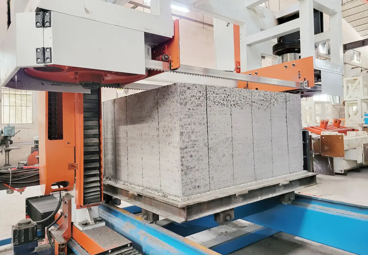
The body needs enough strength to keep its shape under its own weight, transfer forces and cutting loads. When it is too soft for the selected process, the support surface can mark it, edges can tear and the body can move during the cut. Waiting longer strengthens the body, but a harder body can take longer to cut with the same saw configuration. The correct operating window balances clean cutting, safe handling and production rhythm.
Start with the physical-foaming CLC production route. Keep the material batch, density target, mould arrangement and cutting method identified. A window established for one recipe and saw arrangement is not automatically the operating instruction for another product.
What HENGDE’s manufacturer cutting tests actually show
Our 200 m³ two-shift standard proposal includes these manufacturer-test observations. The configuration uses two vertical saw frames and a rotating table: the first direction is cut, the table turns 90°, and the second direction is completed.
| Body strength in the test | Single-body cutting time | Two stacked bodies |
|---|---|---|
| 0.8–1.2 MPa | 3 min 30 sec | 5 min 30 sec |
| 1.3–1.7 MPa | 5 min 30 sec | 8 min |
| 2.0–2.5 MPa | 9 min | 12 min |
| 3.0–3.5 MPa | 12 min | 18 min |
The practical conclusion is that body condition belongs in the capacity calculation. In these tests, moving from the 1.3–1.7 MPa range to 3.0–3.5 MPa increased single-body cutting time from 5 min 30 sec to 12 minutes. These observations do not establish a universal release-strength limit, include all transfer time or prove hourly saleable output.
The complete factory equipment guide explains this proposal’s 16-hour cutting-volume basis, mould fleet and equipment sequence. Keep it separate from the one-8-hour casting-shift basis on the 200 m³ capacity reference page.
Run a trial that separates body condition from machine settings
- Establish the baseline. Identify the recipe, material lots, casting time, body position, curing conditions, release check and product sizes. Use the machine’s approved operating settings and support arrangement.
- Compare release conditions. Select identified bodies at different release stages, keeping the recipe, product and cutting setup comparable. Record the body-condition measurement and test method used by the project team, rather than relying on hours alone.
- Measure the whole result. Time loading, positioning, both cutting directions, rotation, discharge and waiting separately. Measure representative block dimensions and count cutting damage and subsequent stacking damage.
- Refine one factor. Once a suitable body condition is established, compare approved feed settings or support adjustments one at a time. Otherwise, a change in curing and a change in feed can conceal each other’s effect.
Use the defect pattern to choose the next check
| Observed pattern | First comparison to make |
|---|---|
| Soft edges, tearing or body movement | Compare release condition, support contact and transfer handling before increasing cutting speed. |
| Longer cut time as bodies wait longer | Compare body strength, tool condition and the actual cutting portion of the cycle. |
| One direction is consistently worse | Compare positioning and support before and after rotation, then check the relevant saw under the maintenance procedure. |
| Clean cuts, but damaged corners after stacking | Follow discharge and palletizing. A good cut does not establish that the handling sequence is correct. |
These patterns guide the investigation; they are not substitutes for inspecting the actual equipment. HENGDE reviews body condition, cutting setup and connected handling together, so the corrective action addresses the stage causing the loss.
Translate a successful cut into a workable shift
Complete cycle time = loading + positioning + cutting + rotation + discharge + waiting. Count each activity once and use a consistent start and finish point.
For illustration, a four-minute cut plus six minutes of handling and ten minutes of waiting gives a twenty-minute cycle: three cycles per hour, not the fifteen implied by dividing an hour by cutting time alone. These assumed times explain the calculation; they are not HENGDE test results. Removing the waiting bottleneck can be more valuable than forcing the saw to run faster.
Turn the accepted trial into an operator instruction with the release check, approved machine settings, inspection points and action for an unsuitable body. See the Yuyao cutting-line upgrade for real equipment and site photographs; the project is not presented as the source of the test table above.
Establish the cutting and handling sequence for your product
Send your block sizes, recipe and raw-material information, current release condition, cycle timings and close photographs of the defect. Our raw-material assessment team will connect the material review with the cutting configuration and trial plan.