Lightweight Wall Panel Production Process: From Mixing to Finished Panels
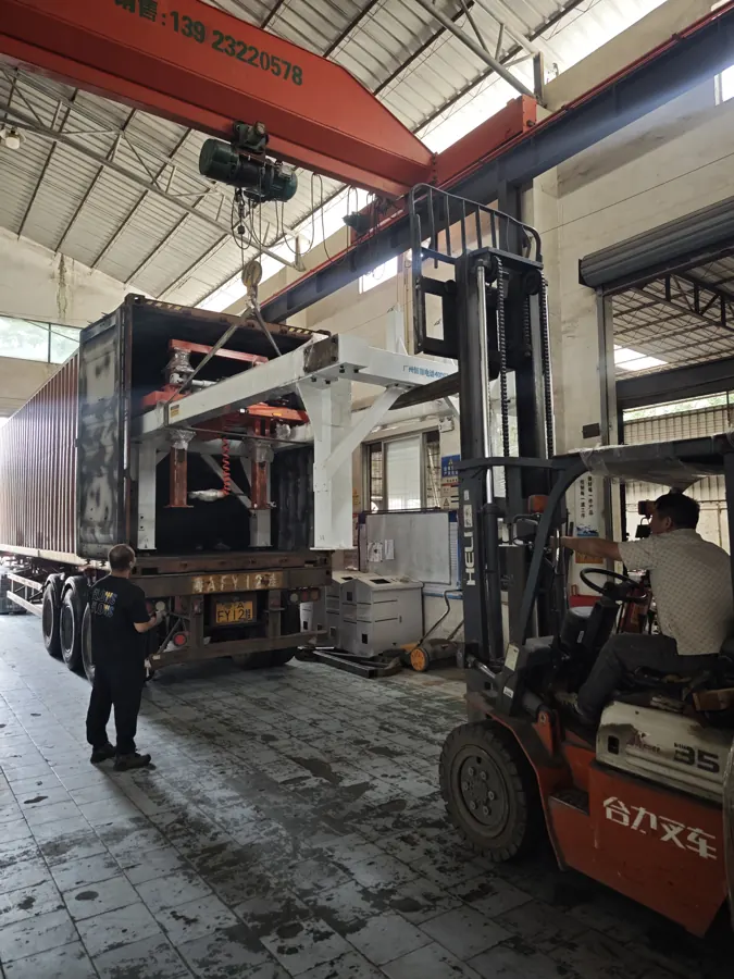
A lightweight wall panel production process is more than a block line with a different mould. Long panel geometry, reinforcement, demoulding, edge finishing and finished-product handling introduce their own equipment and control requirements. The complete route must connect material preparation with long moulds and downstream panel handling. Understanding that sequence helps an investor compare production-line proposals and identify where a “wall panel option” is only a partial add-on. The photographs show real HENGDE equipment at the Mongolia customer factory and finished panels at the Xianning project. They illustrate production stages; they are not the final equipment configuration or layout for a new project.
A lightweight wall panel production process is more than a block line with a different mould. Long panel geometry, reinforcement, demoulding, edge finishing and finished-product handling introduce their own equipment and control requirements.
The complete route must connect material preparation with long moulds and downstream panel handling. Understanding that sequence helps an investor compare production-line proposals and identify where a “wall panel option” is only a partial add-on.
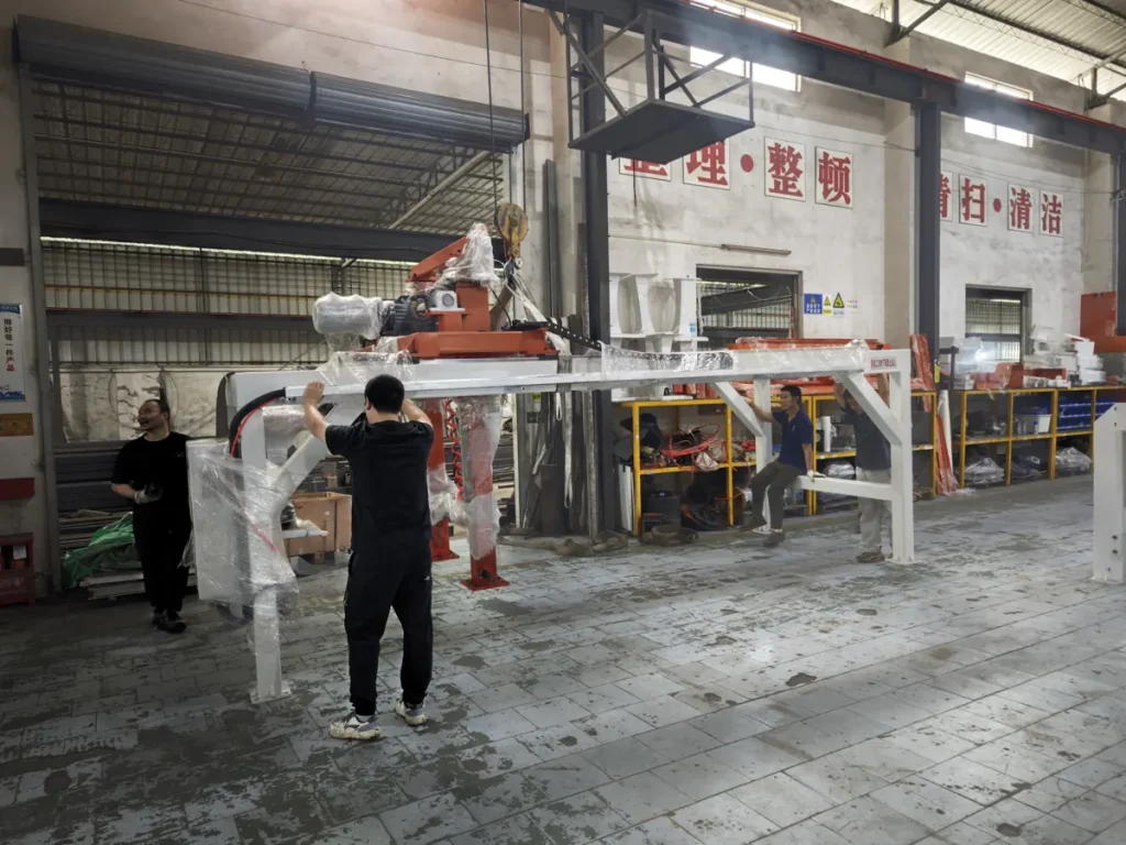
The photographs show real HENGDE equipment at the Mongolia customer factory and finished panels at the Xianning project. They illustrate production stages; they are not the final equipment configuration or layout for a new project.
1. Define the panel before selecting the line
Panel length, width, thickness, edge profile, reinforcement method and target performance affect the process. Product requirements also determine how samples are tested and which local standards apply.
A wall-panel line should therefore begin with confirmed product drawings and material trials. HENGDE does not publish one density or strength value for every country. The customer and engineering team first define the product, raw materials and acceptance method.
2. Prepare and meter the raw materials
The production process starts with receiving, storage, conveying and metering. Cementitious powders, aggregates, water and approved additives must enter the mixer in a controlled sequence. Where physical foam is used, the foaming unit and air supply must be coordinated with the water and mixing system.
Material variation can change slurry viscosity, setting and the condition at demoulding. Representative local samples should be tested before the mixer, pump and dosing arrangement are finalised. See HENGDE’s raw-material assessment process for the information required at this stage.
3. Mix for uniformity and stable transfer
The mixer must disperse the solids and foam without creating damaging segregation. Mixing order, time, water correction and discharge control all affect the slurry entering the panel moulds.
Transfer equipment must then deliver the material over the required distance and elevation. Pump and pipe selection depend on the actual slurry. Access for sampling, cleaning and maintenance should be included in the equipment arrangement.
4. Prepare long moulds and reinforcement
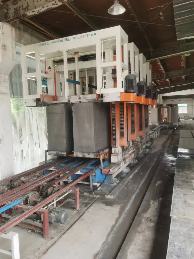
Wall panels are formed in long moulds rather than short block moulds. The mould must support the specified panel geometry and a repeatable release process. Reinforcement frames or rods, where required by the product design, must be positioned and held accurately before pouring.
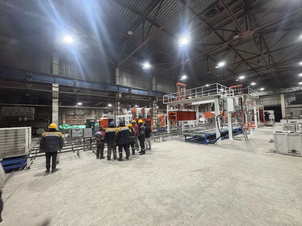
The image above is real project media from a HENGDE wall-panel installation in Mongolia. It shows why mould length, circulation space and access cannot be decided from mixer capacity alone.
Equipment can include reinforcement-rod insertion and removal systems, rod frames, transfer carts and mould accessories. Their final use depends on the approved panel design. Review the reinforcement insertion and removal equipment and related tooling pages for individual machine context.
5. Pour and control the mould-filling sequence
Pouring should fill the long mould uniformly while controlling splashing, segregation and trapped voids. The line arrangement must coordinate the mixer discharge, transfer route, mould position and the time available before the slurry begins to set.
The pouring line is therefore part of a timed production sequence. The quotation should explain whether mould movement, pouring position and return movement are manual, assisted or automatic.
6. Cure to a safe demoulding condition
Non-autoclaved wall panels need controlled curing before demoulding and finishing. The required time depends on the formulation, temperature, panel geometry and handling method. Removing the product too early can damage edges or create deformation; waiting too long can slow the production rhythm and affect cutting or grooving.
Factory planning should provide a protected curing area, predictable mould circulation and clear acceptance checks before a panel moves downstream. The process record should include batch details, time, ambient conditions and the observed demoulding condition.
7. Demould, cut and create the required edge profile
Demoulding equipment supports the long product while separating it from the mould. Downstream machines may cut the panel to length, create grooves or prepare connection details. The exact sequence follows the approved product drawing.
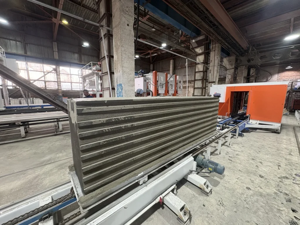
This real Mongolia project image shows HENGDE wall-panel grooving equipment. A grooving machine should be evaluated together with panel support, incoming transfer, dust or debris management and outgoing handling. See the multi-panel slotting machine for equipment-level information.
8. Inspect, handle and stack finished panels
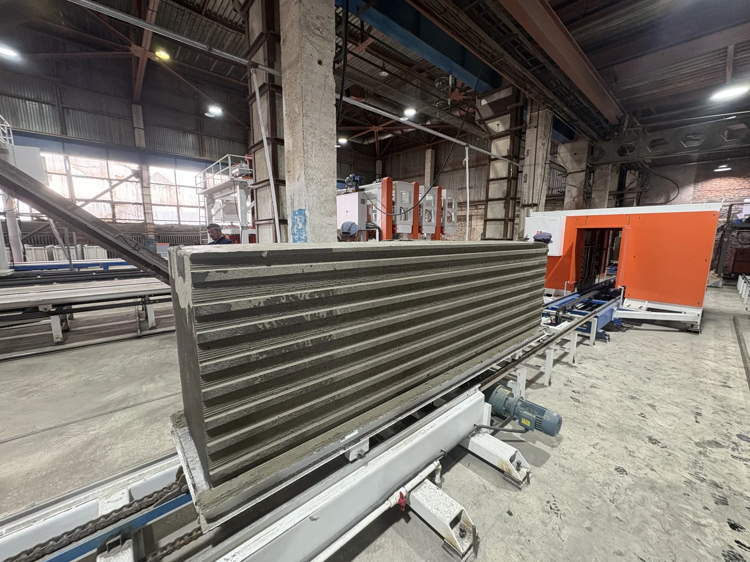
Long panels require stable support during lifting, turning, transfer and stacking. Handling equipment must suit the panel dimensions and condition at that stage. The process should minimise edge impact and avoid point loads that can damage the product.
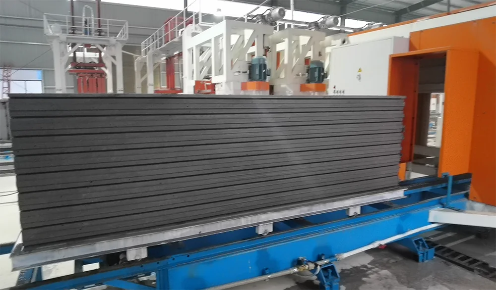
The finished products shown above are real HENGDE project media from Xianning. Production records and finished-product tests—not visual appearance alone—should confirm whether the panels meet the project specification.
Relevant downstream equipment includes the wall-panel clamp, wall-panel transfer car and connected stacking systems.
9. Connect PLC control to real process checkpoints
PLC control can coordinate metering, mixing, mould movement, pouring and downstream equipment. Useful automation is based on defined process checkpoints and interlocks, not simply the presence of a touchscreen.
The control scope should identify sensors, controlled machines, alarm handling, authorised parameter changes and the responsibility for field cabling. Operators still need training in material checks, mould preparation, cleaning, quality records and safe manual intervention.
Questions to ask when comparing wall-panel lines
- Which panel dimensions and reinforcement design does the quotation support?
- Which material-preparation, foaming and mixing equipment is included?
- How many moulds are included and how do they circulate?
- What curing conditions and factory area are assumed?
- Which demoulding, cutting, grooving and handling operations are automatic?
- Which product tests and acceptance checks are the customer responsible for arranging?
- What civil works, utilities, lifting equipment and installation preparation are excluded?
Compare the equipment scope behind a wall-panel line proposal
Use one product drawing and operating plan for every proposal you compare. Ask the supplier to identify what each quoted item does, how it connects to the next stage and which site tasks remain with your team. This helps separate a complete production line from a mixer or a mould package.
| Production stage | Information to confirm in the proposal |
|---|---|
| Materials and mixing | Material trials, feeding and metering scope, mixing sequence, slurry transfer, and physical foaming equipment where the agreed formulation uses foam. |
| Mould fleet | Usable mould volume, included frames and bases, casting and release sequence, cleaning and return route. One reference mould is not a complete production fleet. |
| Curing and occupied space | The material-trial basis for release, mould positions occupied across shifts, intermediate storage and clear movement routes. |
| Reinforcement and finishing | Insertion tooling where the product design requires it, cutting or grooving scope, product support and settings for the agreed panel range. |
| Handling and controls | Demoulding, lifting, transfer and stacking interfaces; controlled equipment, alarms, field connections and operator training. |
| Site and acceptance scope | Drawings and utility information to be supplied, civil and lifting work, installation responsibilities, trial materials, agreed product checks and handover records. |
Compare the 80 m³/day wall-panel reference, 150 m³/day wall-panel reference and 200 m³/day wall-panel reference against that same product and shift basis. These are starting configurations for a project discussion; they do not promise the same qualified output for every formulation or factory. Do not treat the separate 500 m³/day reference as an identical process configuration.
Send the workshop drawing, panel dimensions, materials, working shifts and target qualified output for capacity and layout planning. The resulting layout should connect occupied mould positions with curing, finishing and finished-panel movement.
Plan the process as one connected factory
The HENGDE lightweight wall panel production line page connects the route with real equipment and project evidence. You can also review the Ghana wall-panel project and the wider project library.
To receive a practical configuration, send the intended panel size, project country, raw materials and target output. HENGDE will review the information before recommending mould, mixing, finishing and handling scope.
HENGDE EQUIPMENT & PROJECTS
From our workshop and customer projects
Discuss your production line project with HENGDE.
Share your product, project location, target output and available materials with the HENGDE team.
Discuss Your Project