


Mixing
Metered solids, water and preformed foam enter the selected mixer.

HENGDE · EQUIPMENT MANUFACTURER
Plan the mixing, mould circulation, curing, cutting and handling stages around your block and factory. Start with the equipment configuration and layout, then define the supply scope.
Delivery lead time: 40–50 working days.
THE LINE, AS A CONNECTED PROCESS
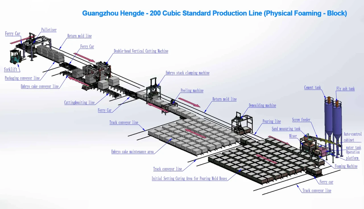
Review material flow, mould circulation, cutting and finished-product handling on the engineering layout.
Illustrated arrangement for the 200 m³/day project discussion. The final equipment schedule and site layout must refer to the same approved configuration.
FROM MATERIAL TO FINISHED BLOCK
Six connected stages. Scroll to see the equipment behind each step, or select a stage.


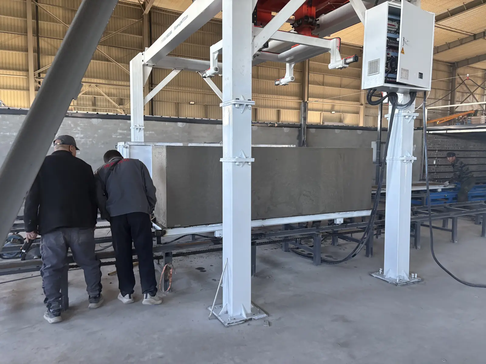
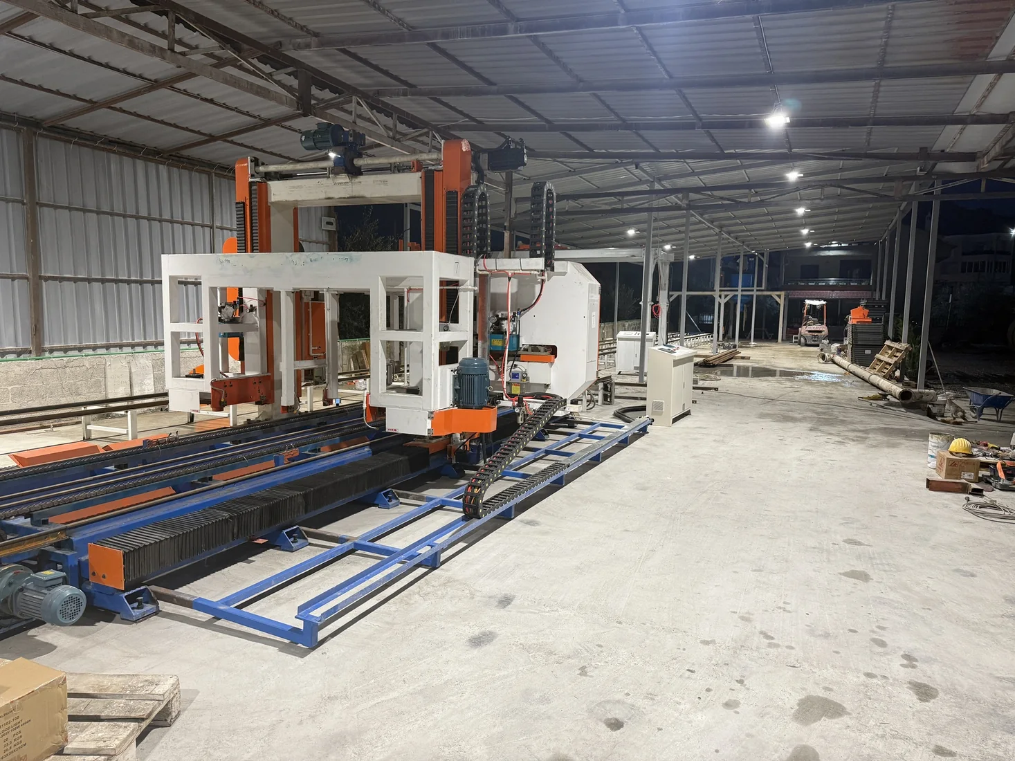
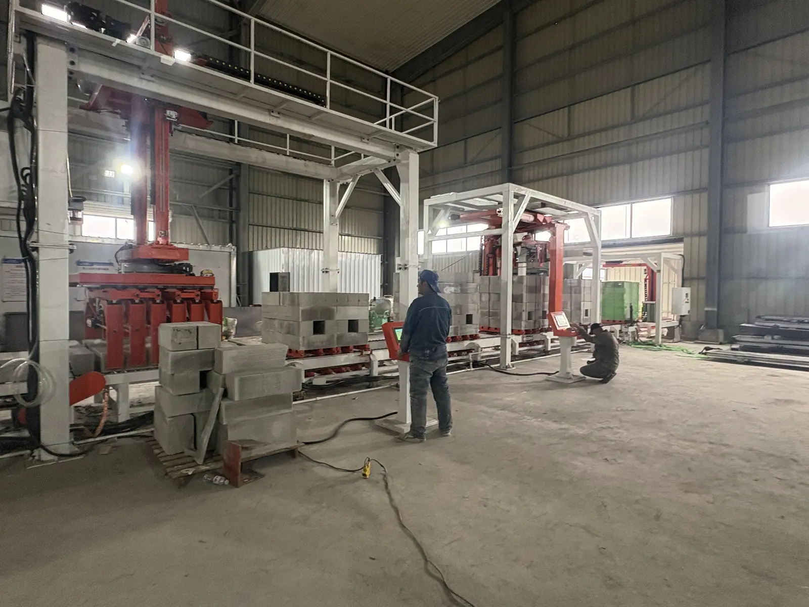
Process examples from HENGDE equipment and project records. Photographs do not all show one factory or one configuration.
Metered solids, water and preformed foam enter the selected mixer.
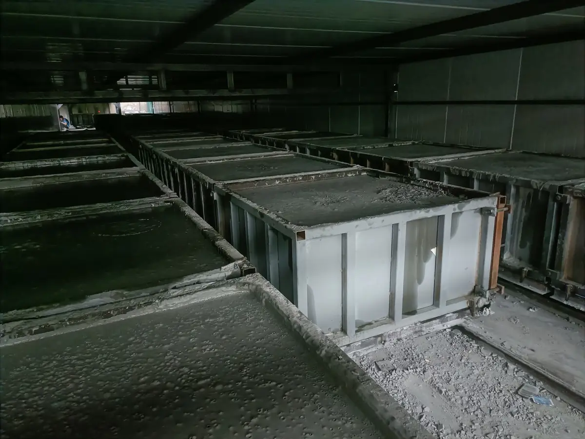
The mixed material is discharged into the mould circulation line.
Mould circulation and curing are matched to the product and site conditions.
Release and transfer the green body at the required handling condition.
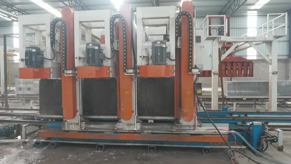
The cutting sequence follows the product dimensions and green-body condition.
Transfer and stack the cut products for the next handling stage.
EQUIPMENT BY PRODUCTION STAGE
Existing HENGDE catalogue equipment, organized by function. The project-specific equipment schedule defines the final supply scope.
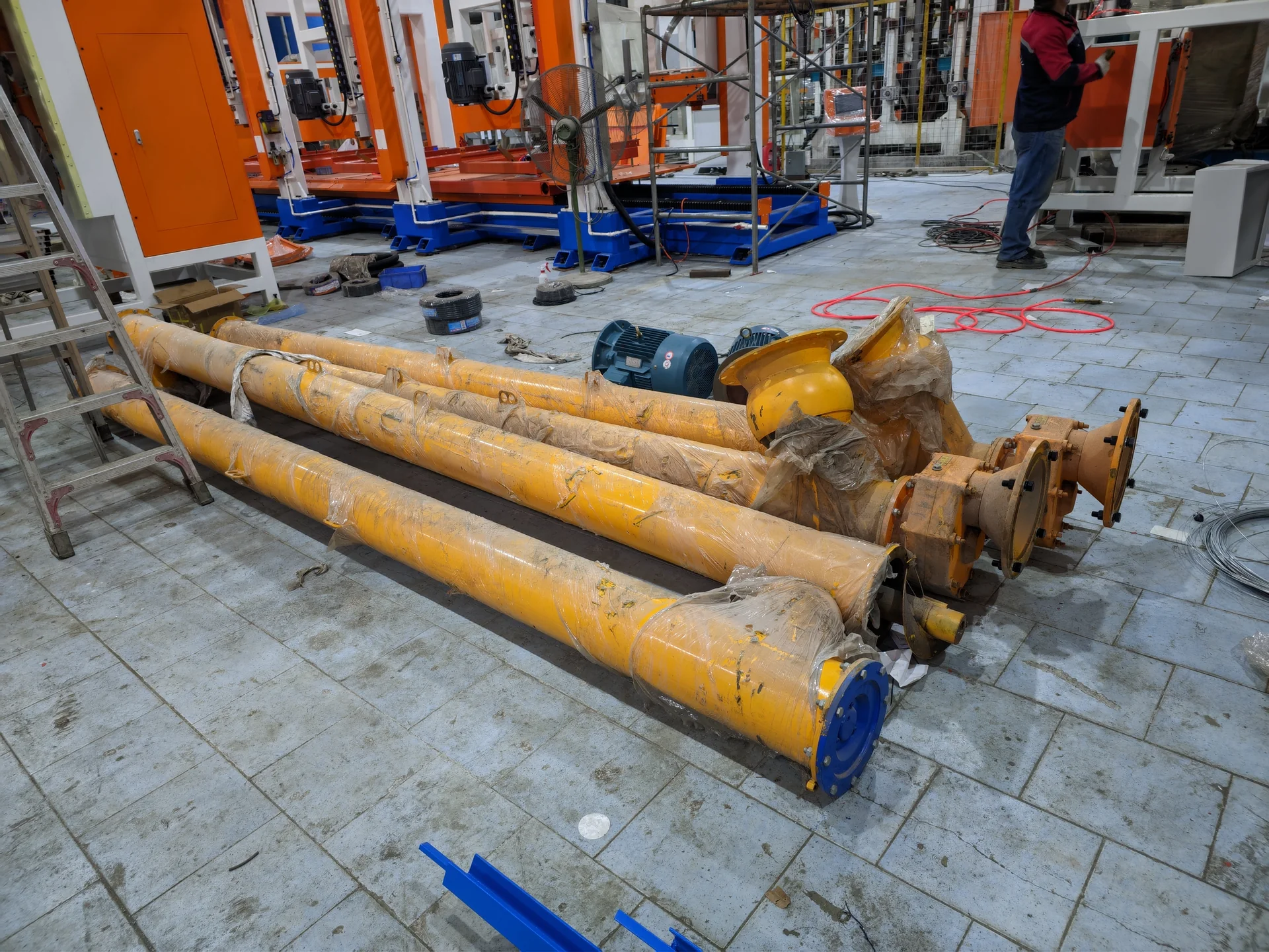
Moves compatible powder materials from storage toward the metering section.
View equipment →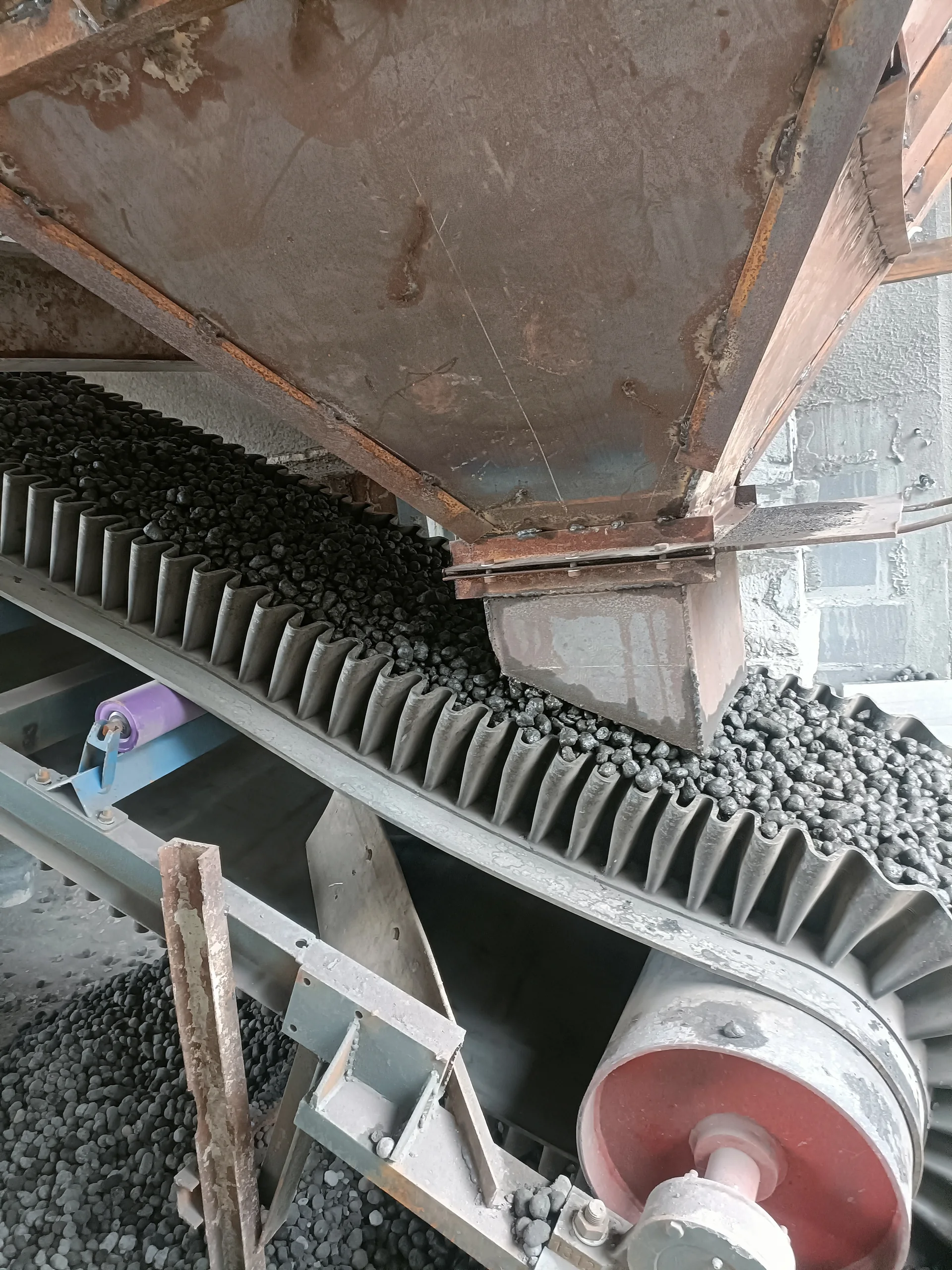
Connects compatible bulk-material feeding with the preparation and metering stage.
View equipment →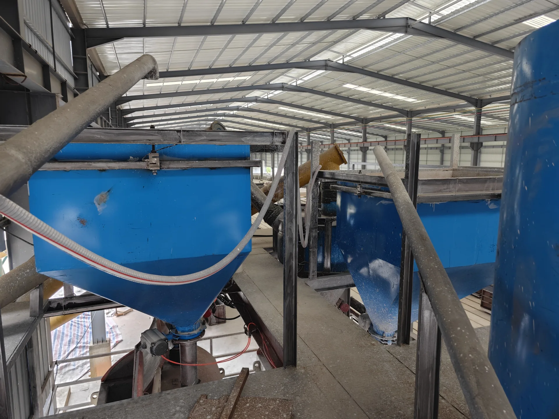
Buffers and meters compatible material between conveying and batch preparation.
View equipment →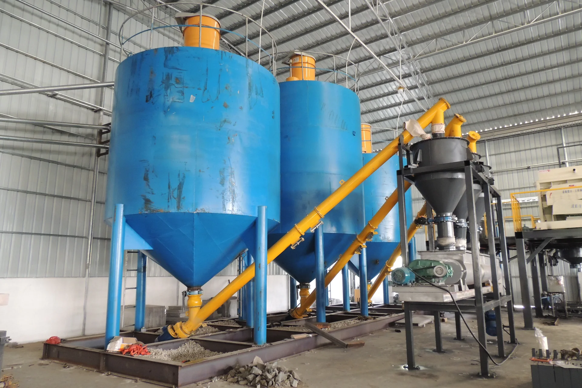
Measures the confirmed powder input for each production batch.
View equipment →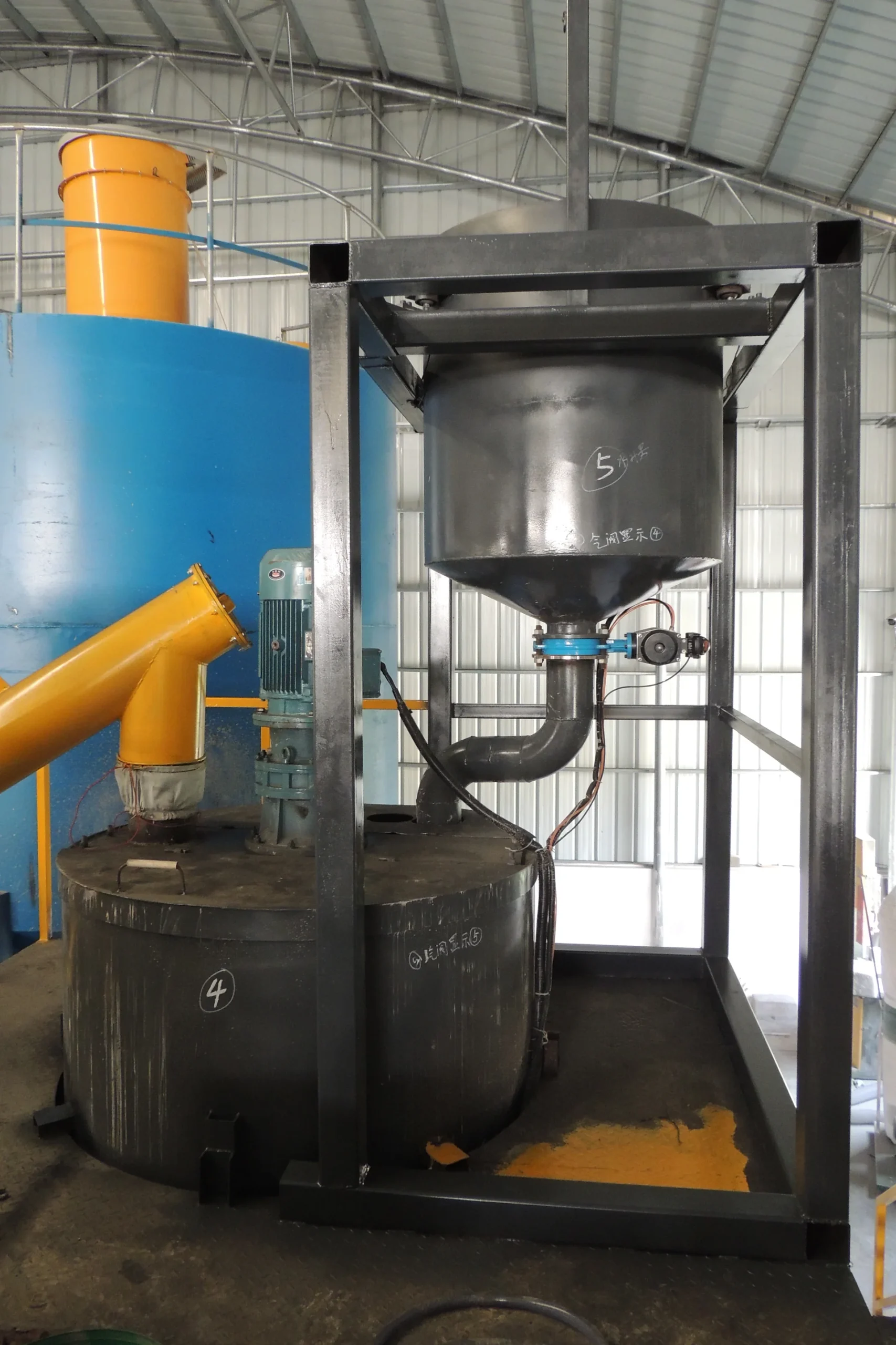
Stores and releases the confirmed water quantity for the controlled batch.
View equipment →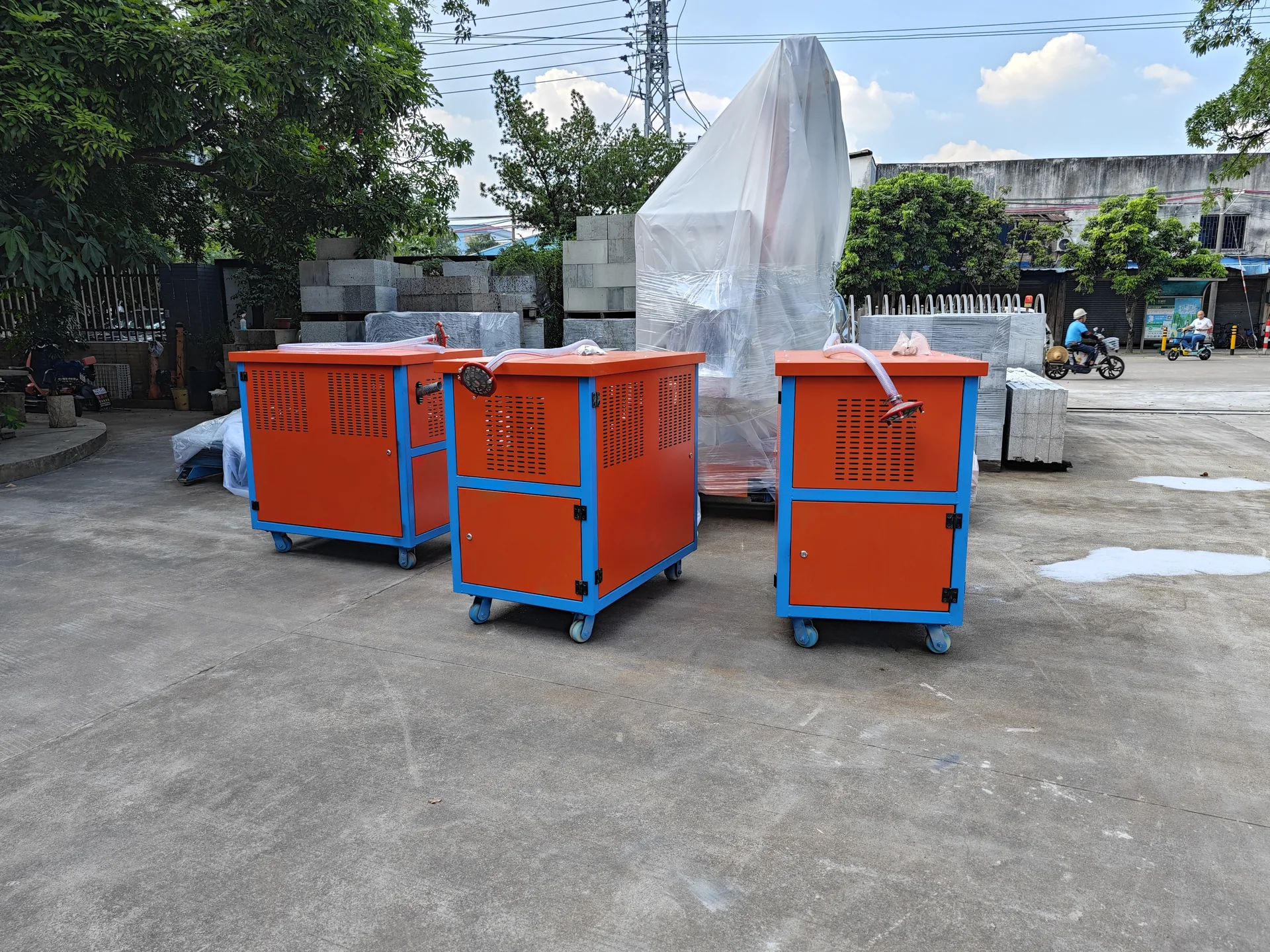
Prepares physical foam for a confirmed CLC foam-concrete route; it is not an aluminium-powder NAAC machine.
View equipment →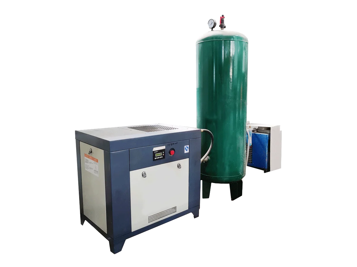
Supplies compressed air to the confirmed foaming and pneumatic scope; the 50 and 100 m³/day references use different variants.
View equipment →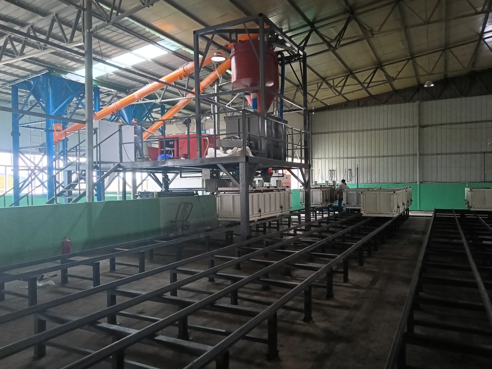
Supports the feeding, metering and mixing arrangement; approved engineering drawings specify customer-supplied steelwork.
View equipment →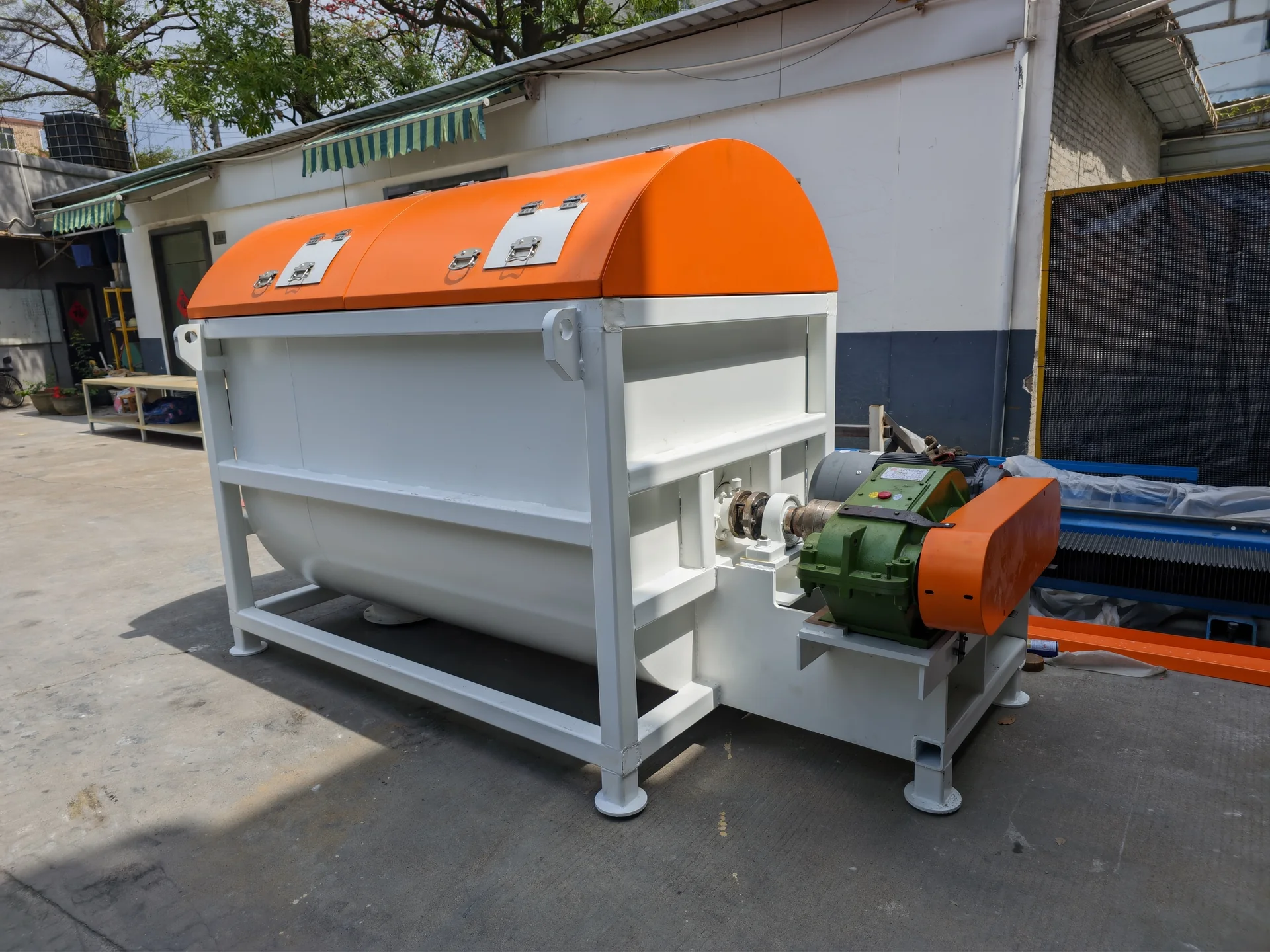
Combines the confirmed solids, water and route-specific lightweight constituent according to the approved batch sequence.
View equipment →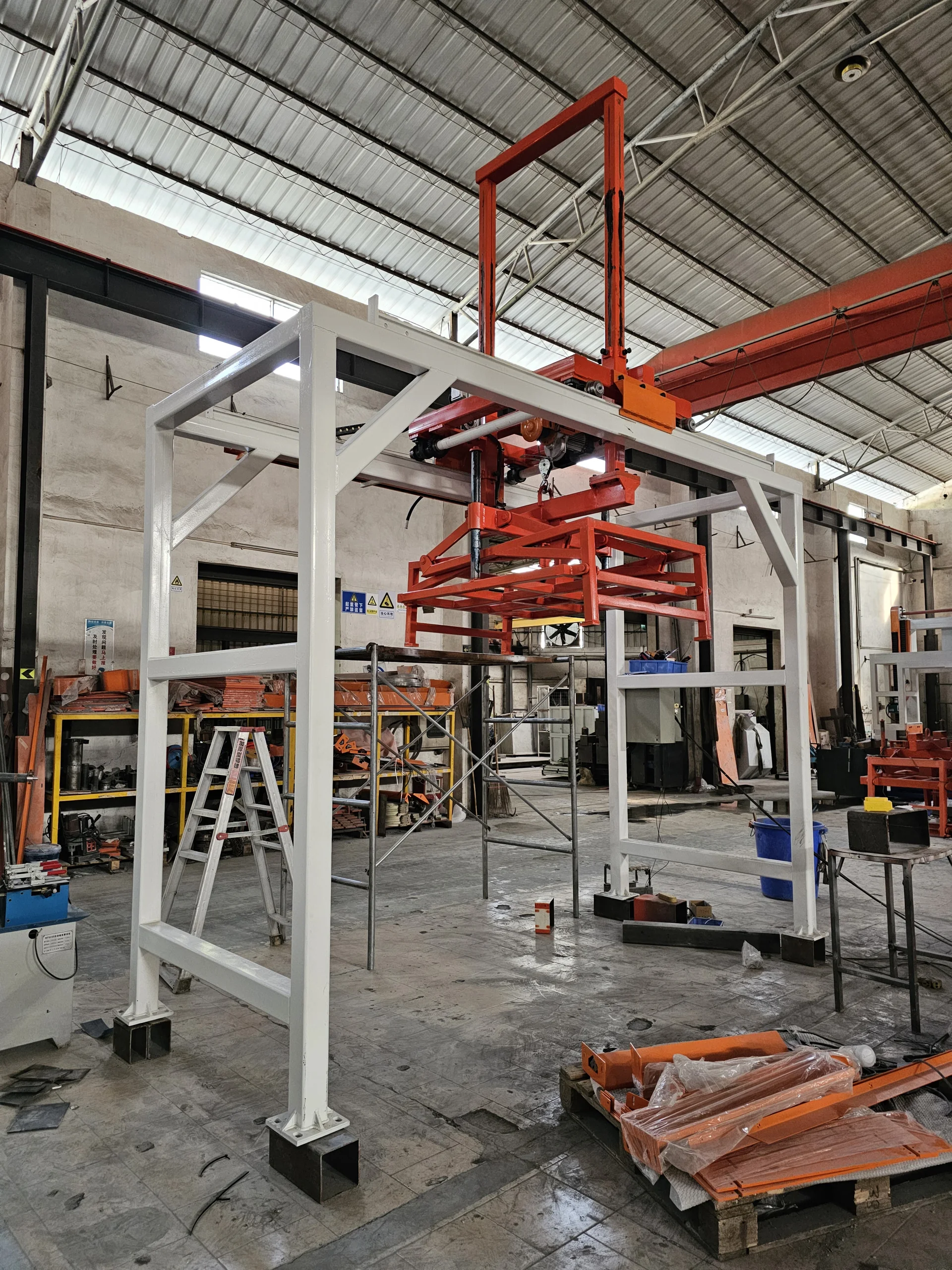
Separates and lifts the mould or green product at the confirmed demoulding condition.
View equipment →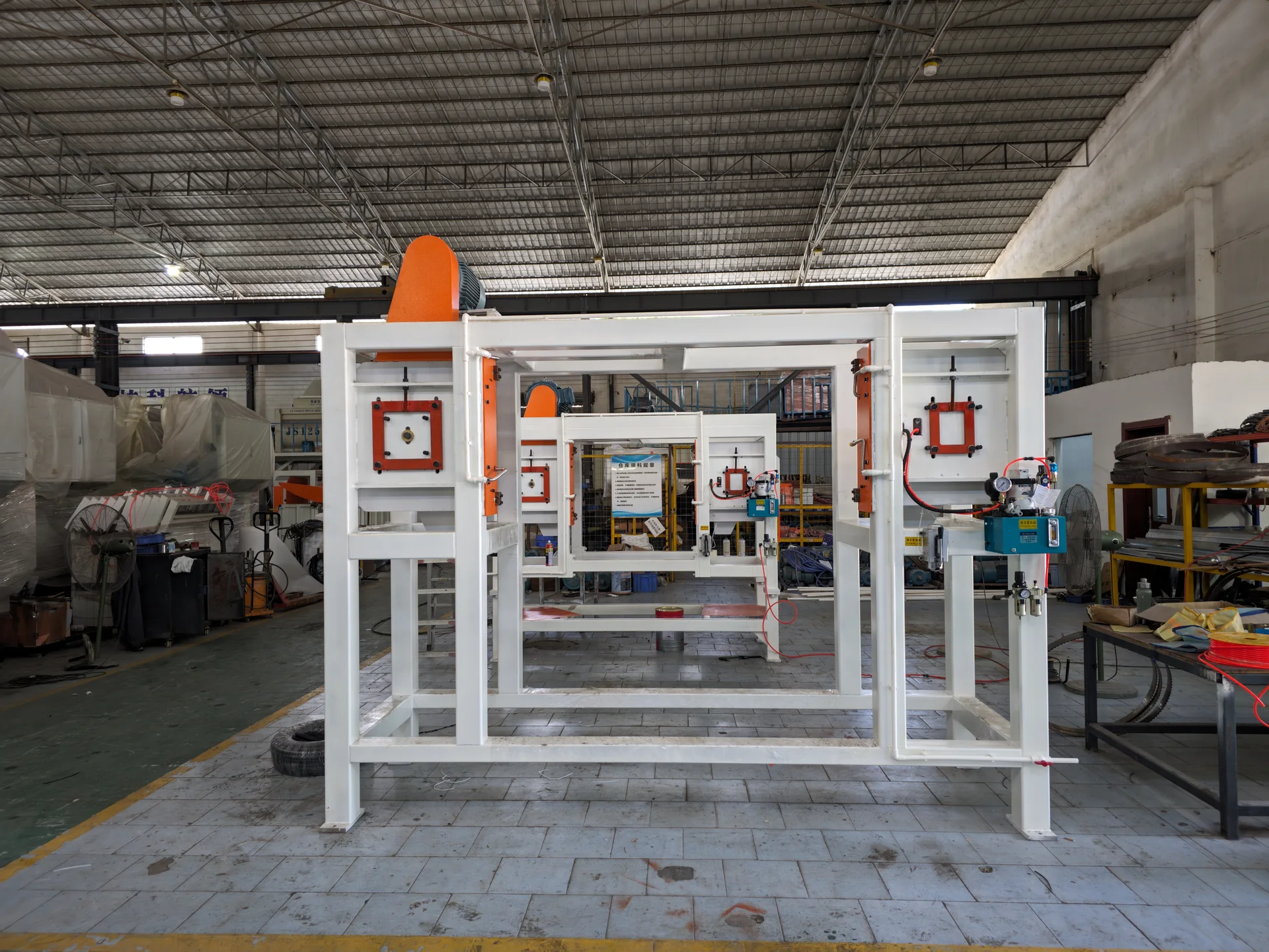
Removes the confirmed surface layer before dimensional cutting or finishing.
View equipment →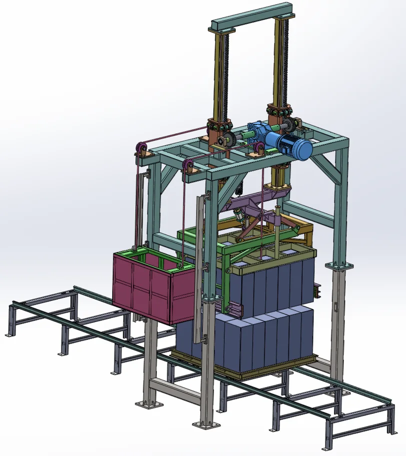
Lifts or grips blocks according to the confirmed product condition and transfer sequence.
View equipment →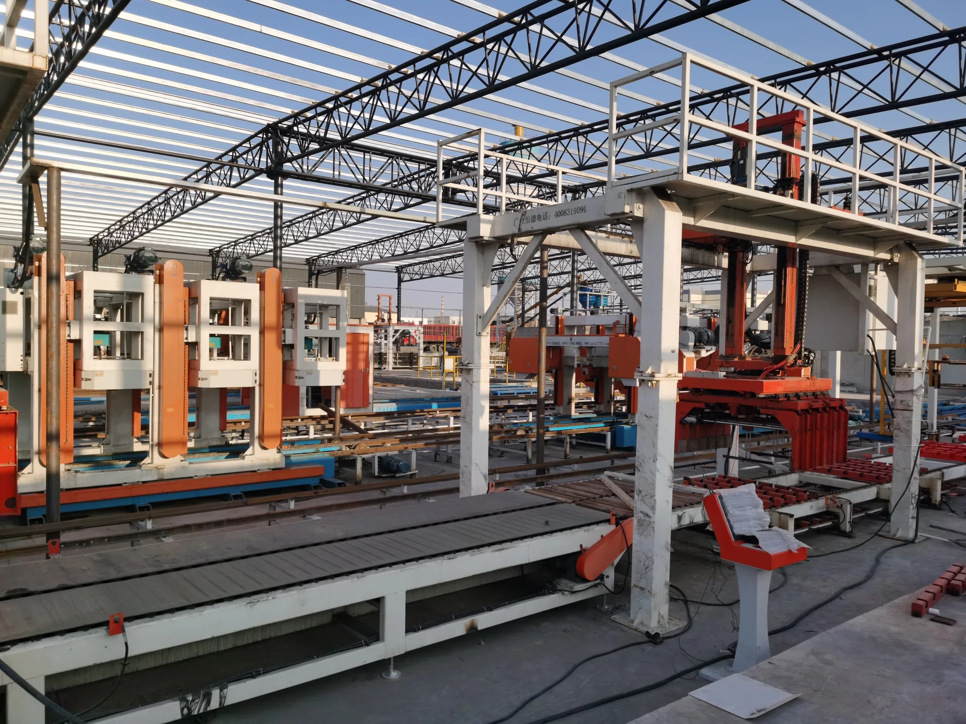
Lifts and stacks finished product according to the approved handling pattern.
View equipment →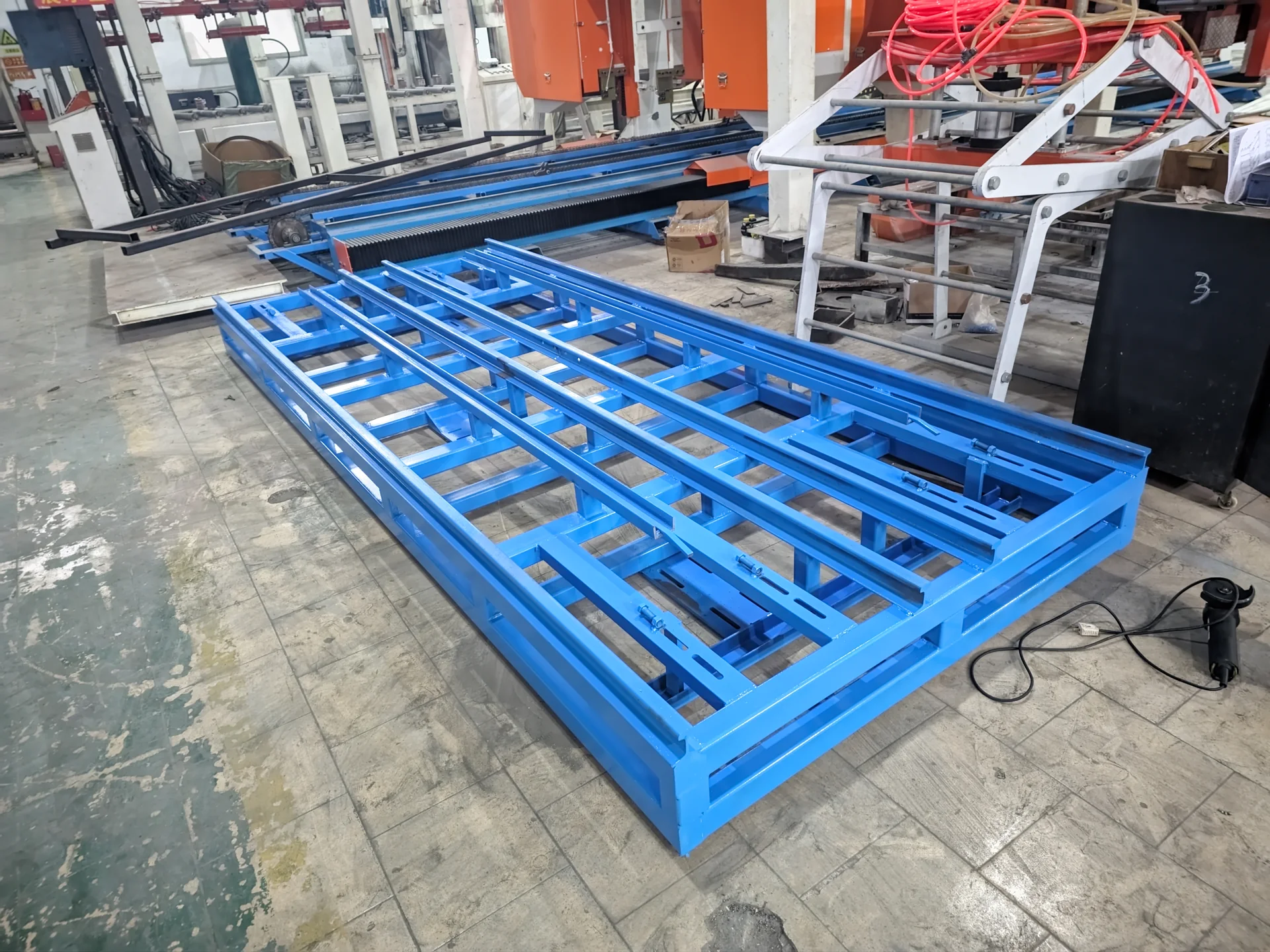
Covers capacity-specific transfer-cart or mould-circulation sections without merging their models or parameters.
View equipment →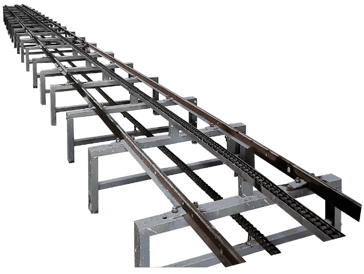
Provides powered movement through the listed demoulding station.
View equipment →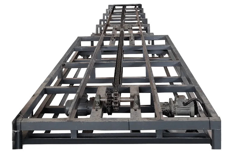
Returns empty moulds for cleaning, preparation and the next pouring cycle.
View equipment →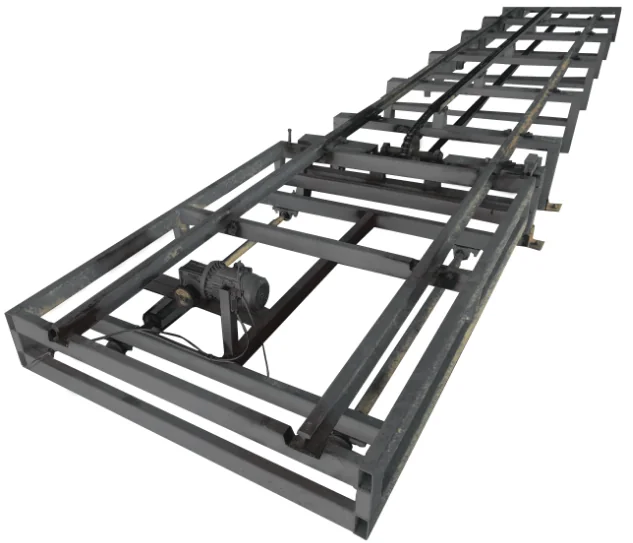
Moves prepared moulds through the listed pouring position.
View equipment →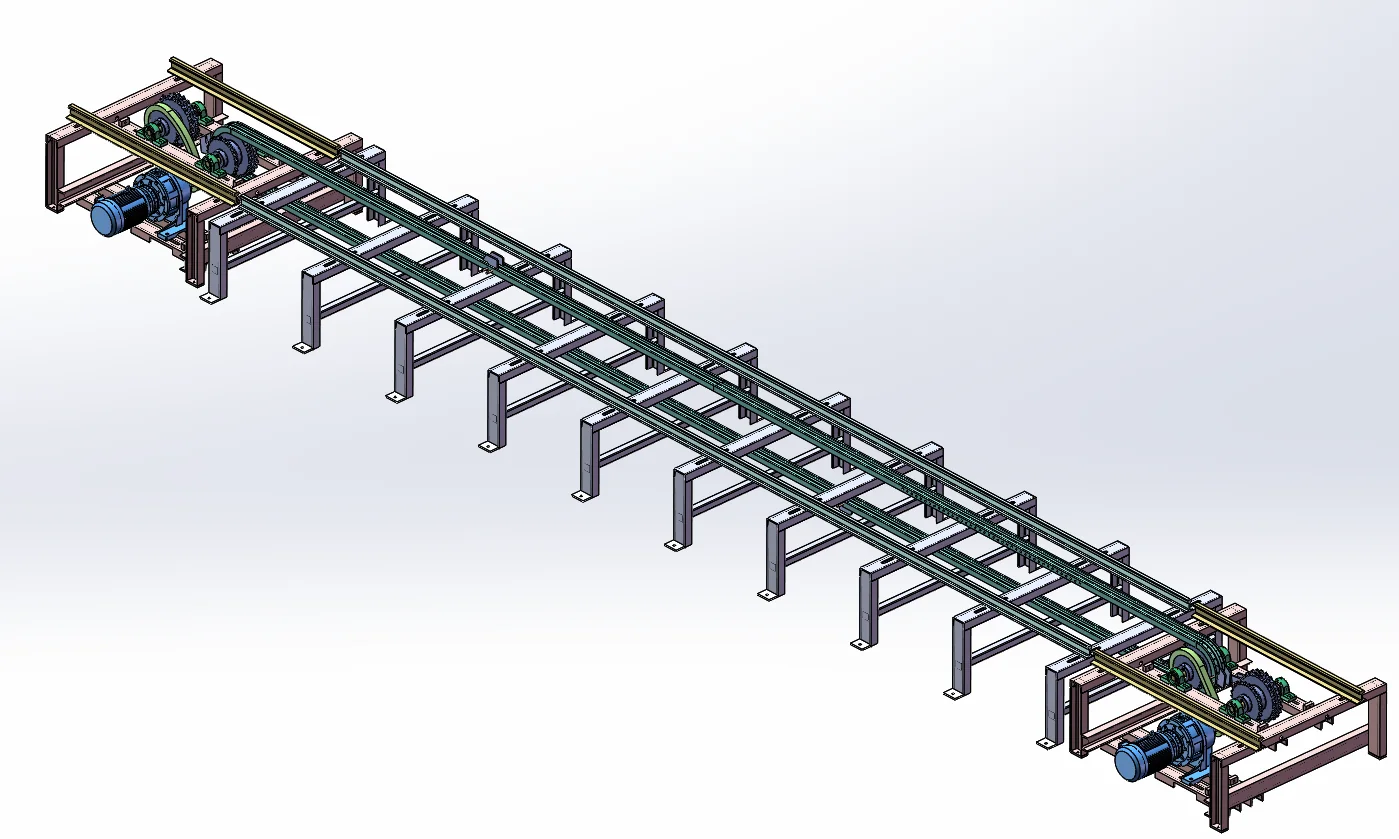
Moves confirmed material or carriers through the listed automatic feed stage.
View equipment →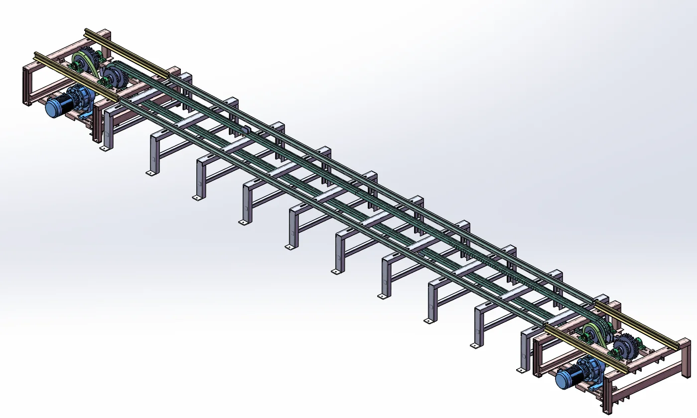
Moves the confirmed carrier or product out of the connected station.
View equipment →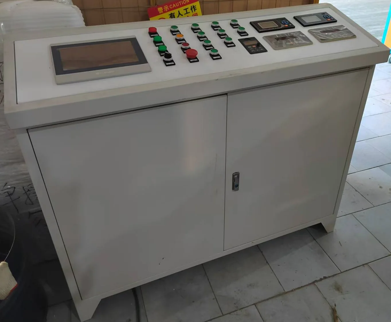
Coordinates the confirmed line sequence, interlocks, commands and alarms.
View equipment →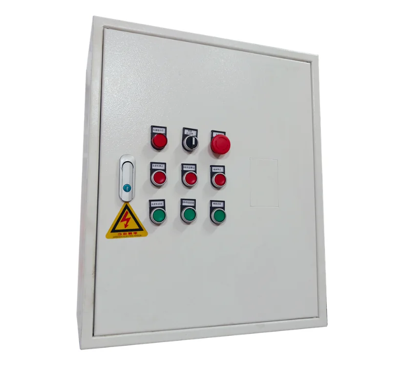
Controls the delivered physical-foaming equipment scope.
View equipment →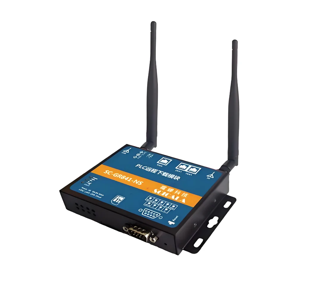
Provides the listed remote command functions for the confirmed controls scope.
View equipment →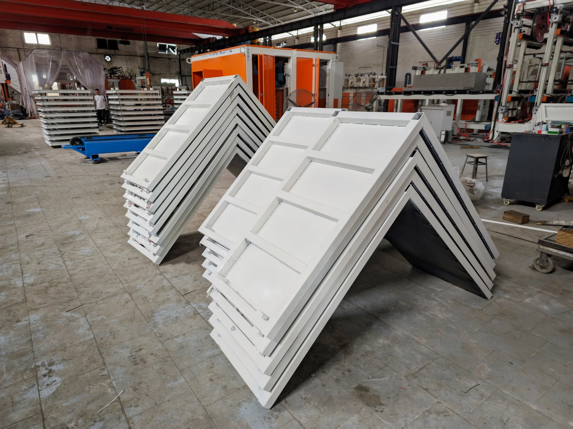
Forms the lightweight block billet; the delivered geometry follows the selected product.
View equipment →Match the equipment to your block sizes, raw materials and available space. Get the equipment schedule and layout
REAL MACHINES. REAL PROCESS.
Watch mixed material discharge from the mixer into a mould during a HENGDE material trial. Silent excerpt from the original trial footage.
Open the player, then use its play and pause controls. No automatic playback.
Open video ↗CONNECTED EQUIPMENT AT A CUSTOMER SITE
Real site photographs illustrate equipment connections. The project record identifies its own scope.
The Xianning record shows connected HENGDE equipment at the customer site. Use it to understand equipment connections and material flow while discussing your own layout.
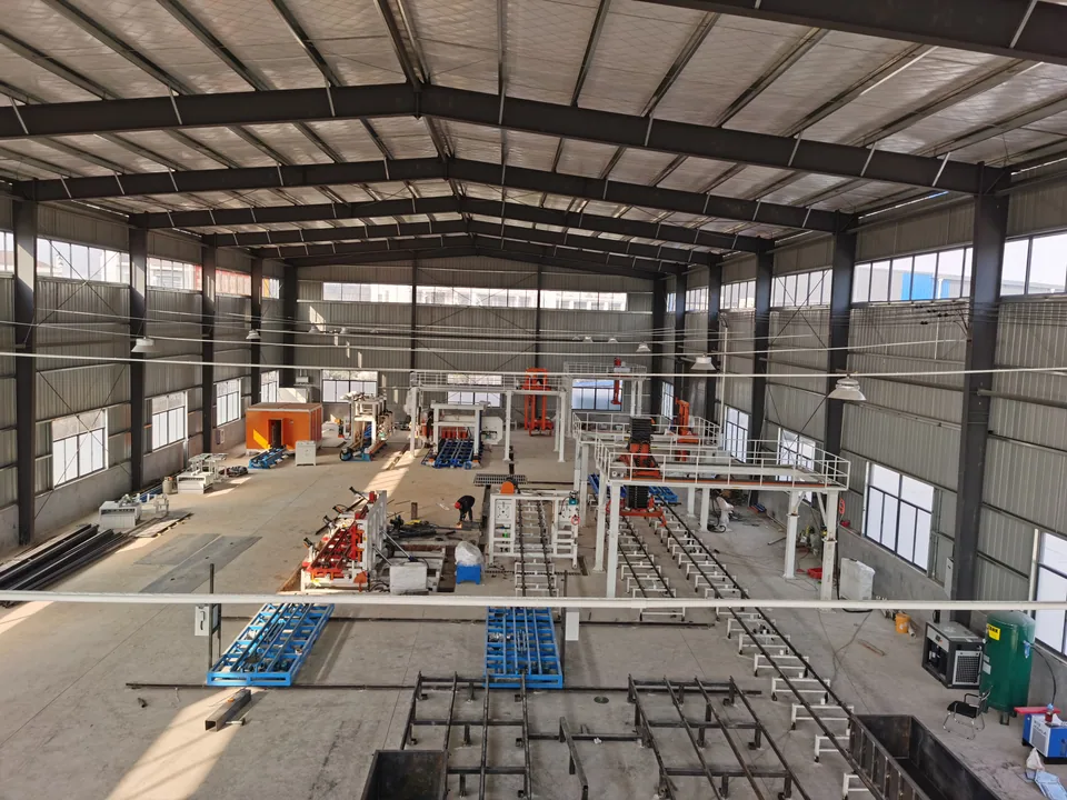
View the Xianning project record
The Ghana wall-panel record documents loading and shipment; its project and equipment scope are separate from this block-line configuration.
CUSTOMER EQUIPMENT & DELIVERY RECORDS
Explore customer equipment and delivery records.
Project 1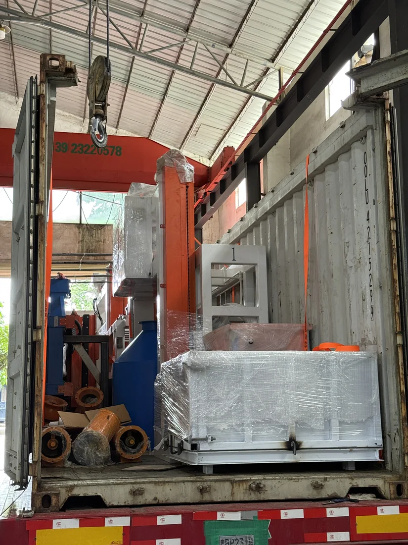
Indonesia · Equipment shipped
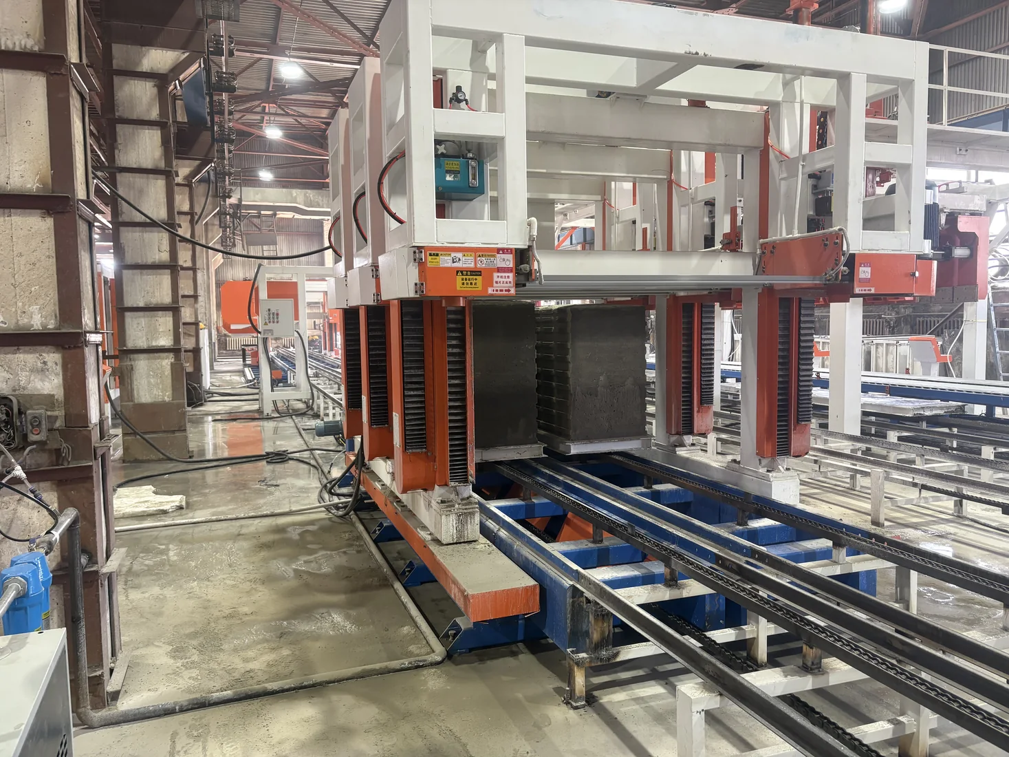
Mongolia · Equipment installed at site
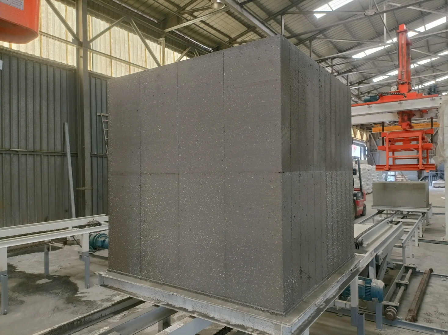
South Africa · Production-site media available
Albania · Line operating at site
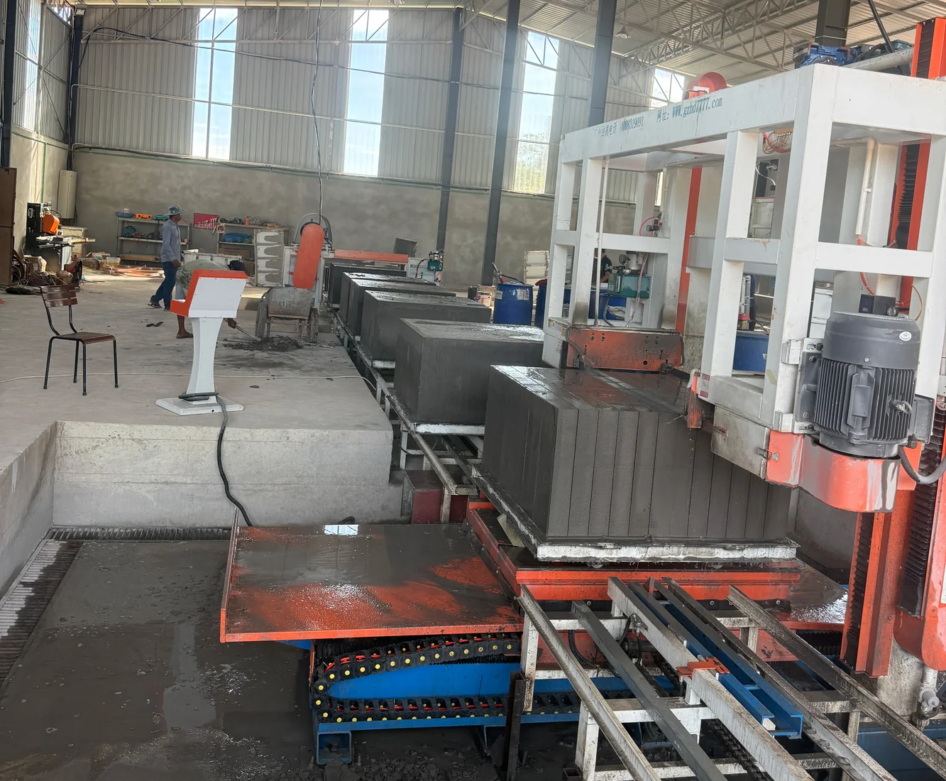
Cambodia · Production-site media available
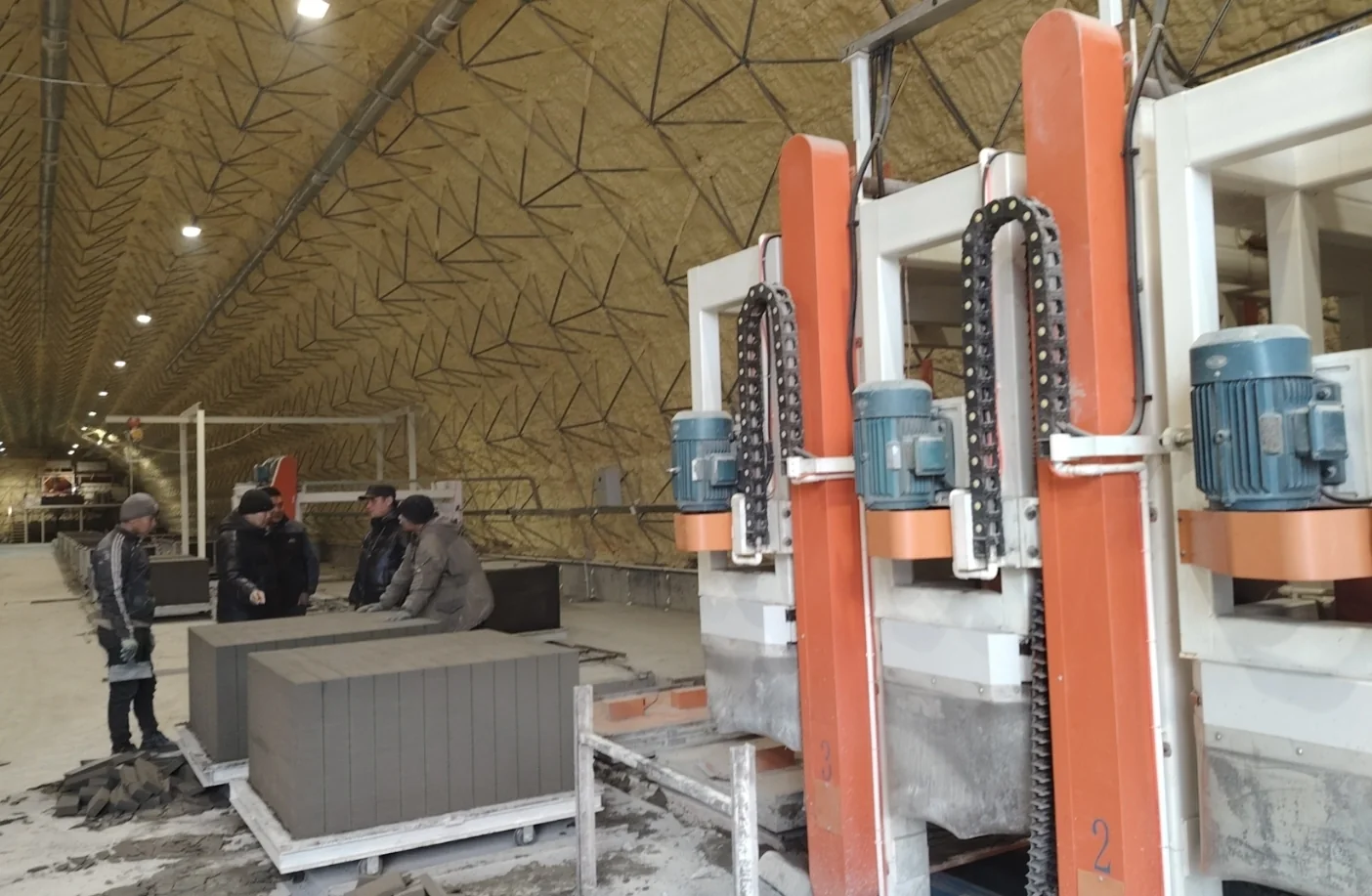
Kyrgyzstan · Production media available
Each record retains its own product, configuration and documented stage. Shipment evidence is not presented as evidence of stable production.
PREPARE YOUR FACTORY PROPOSAL
Product, raw materials, site and equipment scope — keep the engineering detail available without losing the production story.
Bring the finished-block specification you intend to sell: dimensions, intended use and any applicable performance requirements. Add your local raw-material information and the purpose of the factory. These inputs guide the process, mould arrangement and cutting system.
The 200 m³/day figure is a design-capacity basis. Shift planning, mould circulation, curing, handling and the proportion of conforming products all affect actual output. The equipment list and these conditions must describe one consistent configuration.
Share the block you plan to make · View the engineering layout
Review the layout with these stages in mind · Explore cutting systems
HENGDE organizes the proposal by production stage, equipment interface and supply responsibility. The final equipment schedule identifies included items, options and customer-prepared work.
| Equipment group | What the configuration must specify | Supply boundary to record |
|---|---|---|
| Material preparation and mixing | Material storage, feeding, metering, mixing and connection to casting. | Supplied equipment, site-prepared storage and utility connections. |
| Moulds and circulation | The product arrangement, mould movement, curing, demoulding and return path. | Mould configuration, handling interfaces and any customer-prepared areas. |
| Cutting | Billet dimensions, finished-block specification and the cutting sequence. | The cutting equipment, associated handling and any selected options. |
| Transfer, stacking and controls | How materials move between stages and how equipment operation is coordinated. | Automation scope, interfaces and items provided at the site. |
Request the equipment configuration. Have the proposal distinguish included equipment, optional equipment and customer-supplied work.
Send the source and available specification of each proposed raw material, photographs and any existing test reports. If samples are sent, label each with the source, batch and sampling date. Keep different sources identifiable instead of combining them into an untraceable sample.
HENGDE reviews material composition, grading, moisture and source consistency, then defines representative sample trials. The trial record identifies mixing, mould filling, curing and finished-product results, giving the configuration discussion a traceable material basis.
| Information to provide | Why it affects the layout |
|---|---|
| Building dimensions and clear height | They define the space available for equipment, movement and handling. |
| Columns, doors and vehicle access | They affect equipment placement, material delivery and finished-product movement. |
| Raw-material, curing and finished-product areas | They must connect to the process without treating all floor space as equipment space. |
| Available electrical supply and water | The project needs defined connection points and utility requirements for the selected configuration. |
| Planned work shifts and available roles | They help define operating responsibilities, handling and the automation discussion. |
Ask for the layout, utility requirements and operator responsibilities for the same equipment configuration. Installed power is an equipment specification; it is not a statement of actual electricity consumed per hour.
The equipment delivery lead time is shown above. Shipping, site installation, commissioning and training are specified separately in the project proposal.
For the proposal, identify the equipment supply, shipment arrangements, installation, commissioning, operator training and the work to be prepared by the customer. Discuss the scope, responsibilities and any associated costs before finalizing the project.
Product specification, raw materials, mould arrangement, cutting method, automation and supply boundaries affect the equipment configuration and quotation. A line name or capacity figure by itself does not define the complete supply.
Start with the short form below. Include the project country, target product and current stage; add the output target, raw-material details or site information when available. Ask for the equipment configuration, factory layout and formal quotation together so you can compare the same scope.
YOUR NEXT STEP
Get the equipment configuration, factory layout and a formal quotation for your project.
Discuss your project
A few details give our team the right starting point for your production line proposal.
Delivery lead time: 40–50 working days.