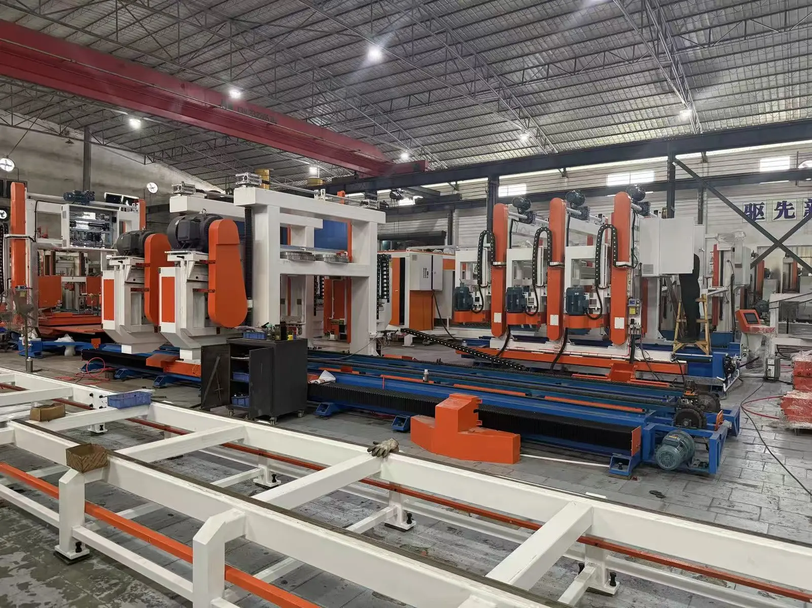
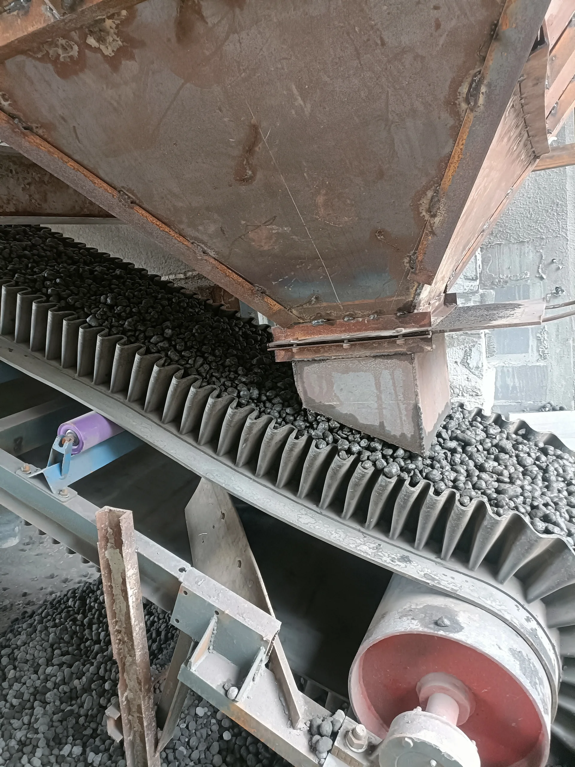
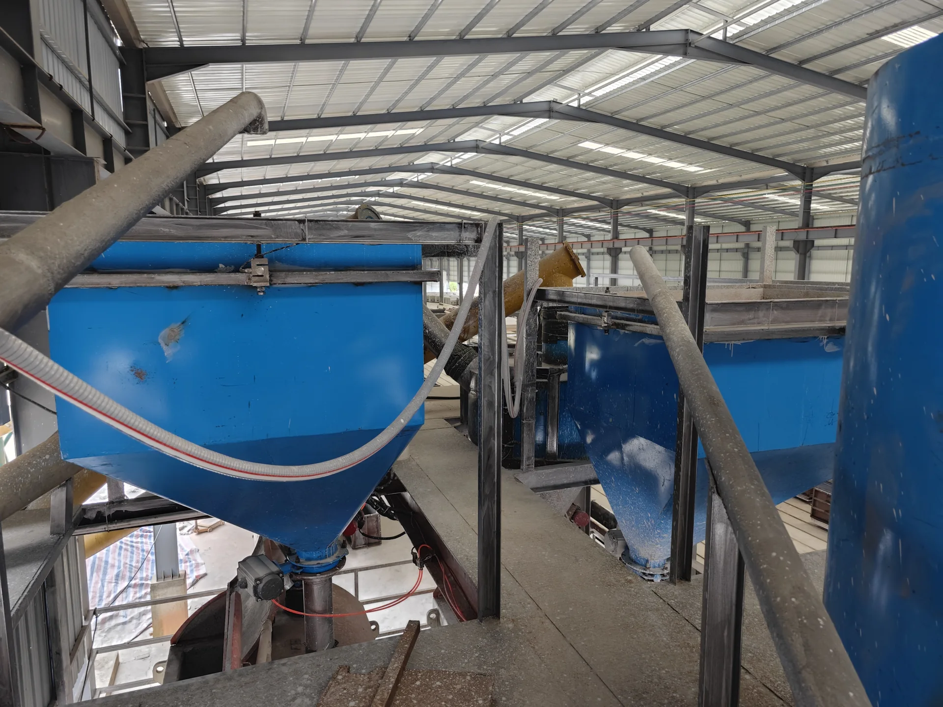
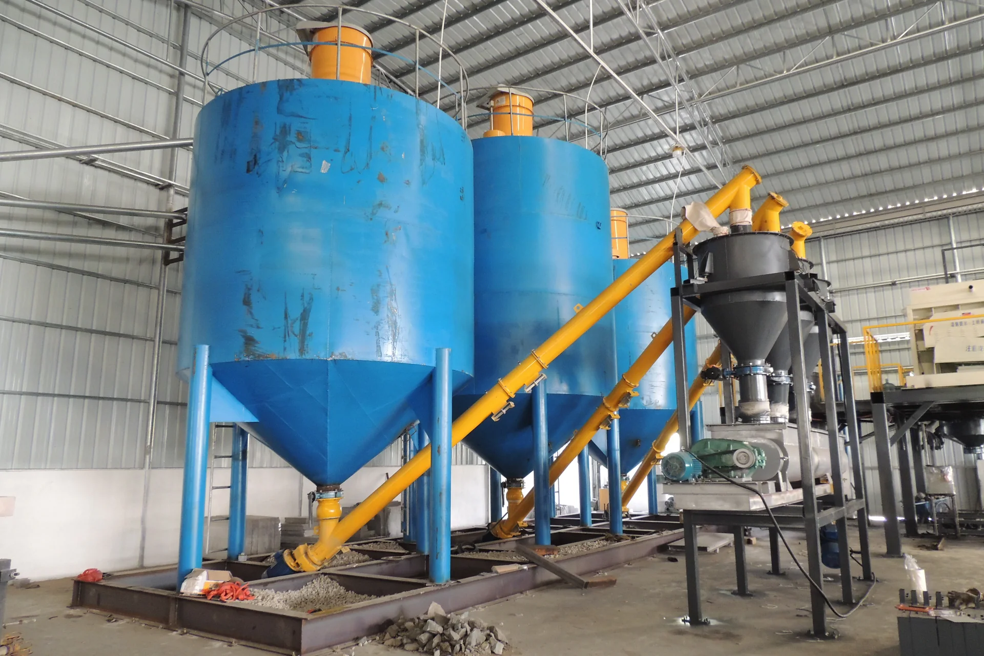
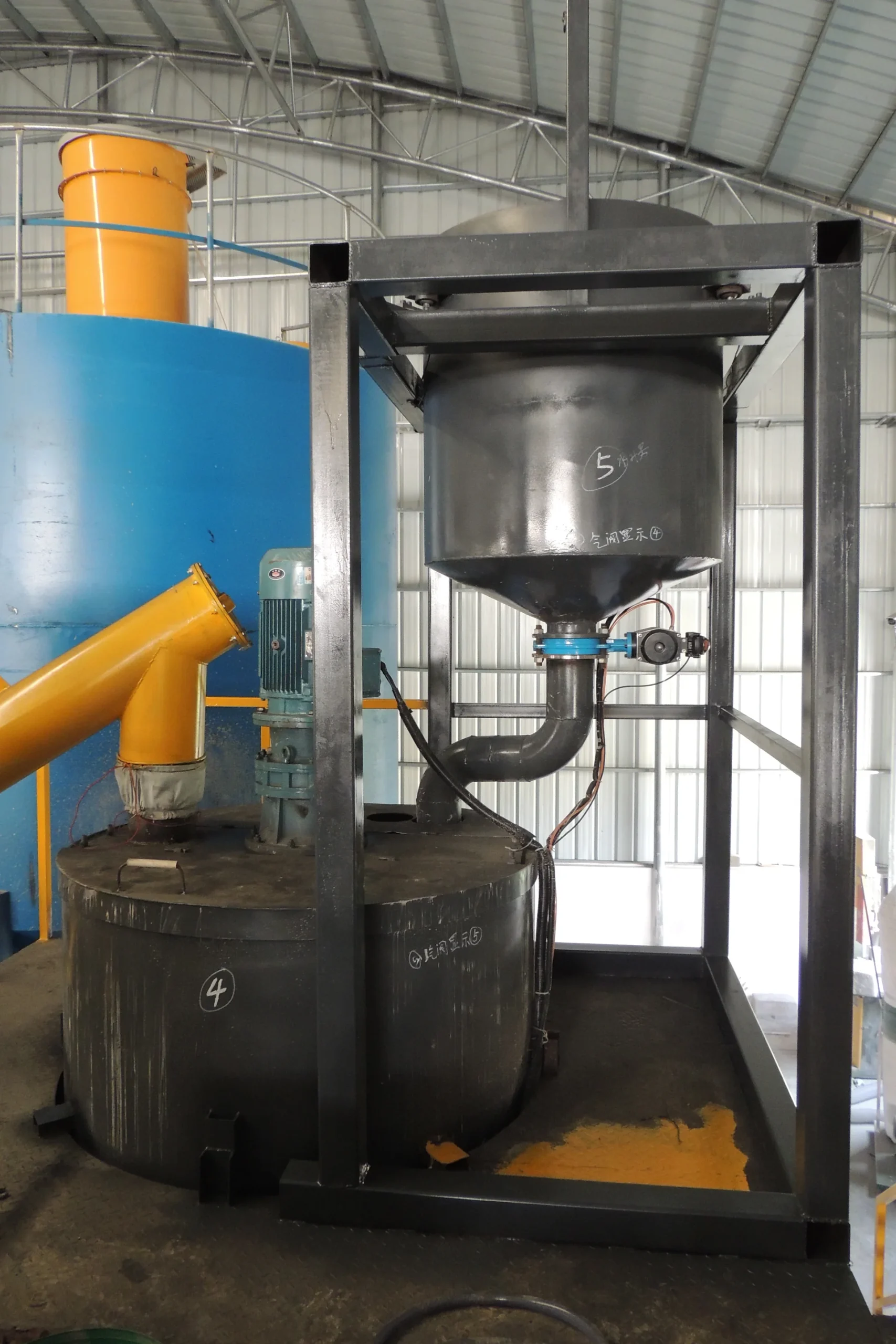
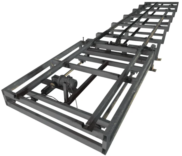
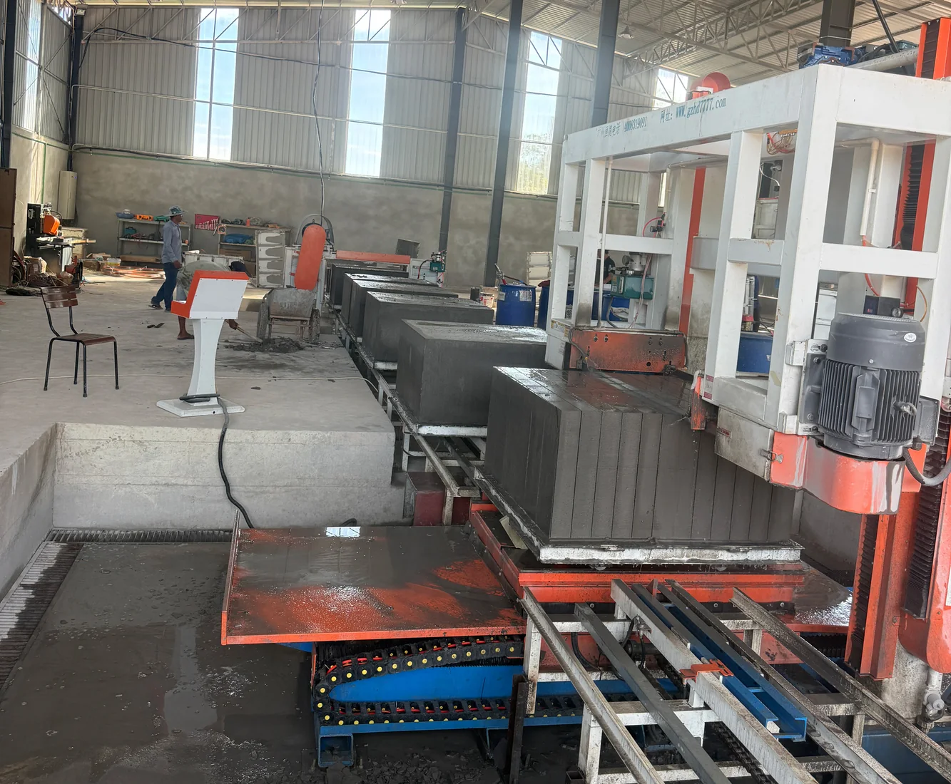
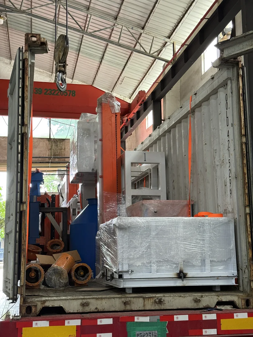
CLC PHYSICAL-FOAMING LINE

300 m³/day CLC Block Production Line

Delivery lead time: 40–50 working days.

PROCESS ROUTEPhysical foaming · Non-autoclaved curing

CLC / foam concrete block production using physical foaming and non-autoclaved curing. Explore the line visual, production stages, equipment configuration, project examples and installation support.

Get a Production Line Proposal
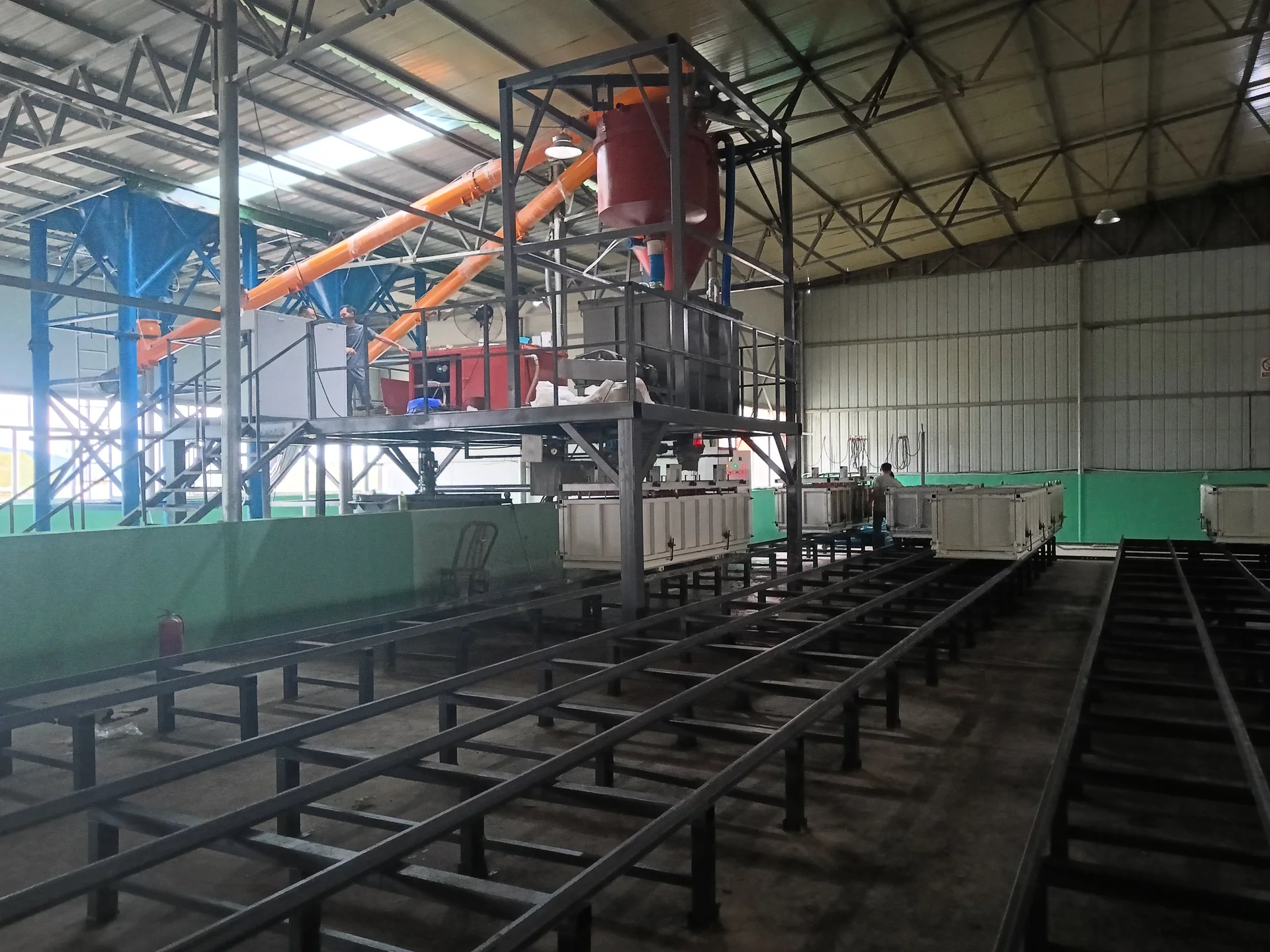
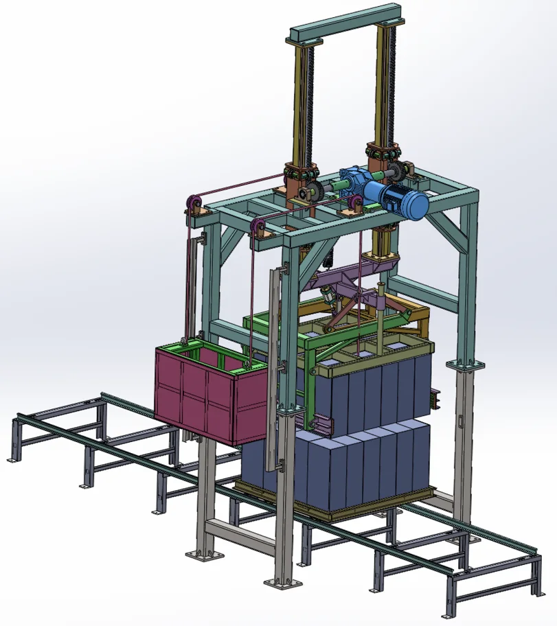
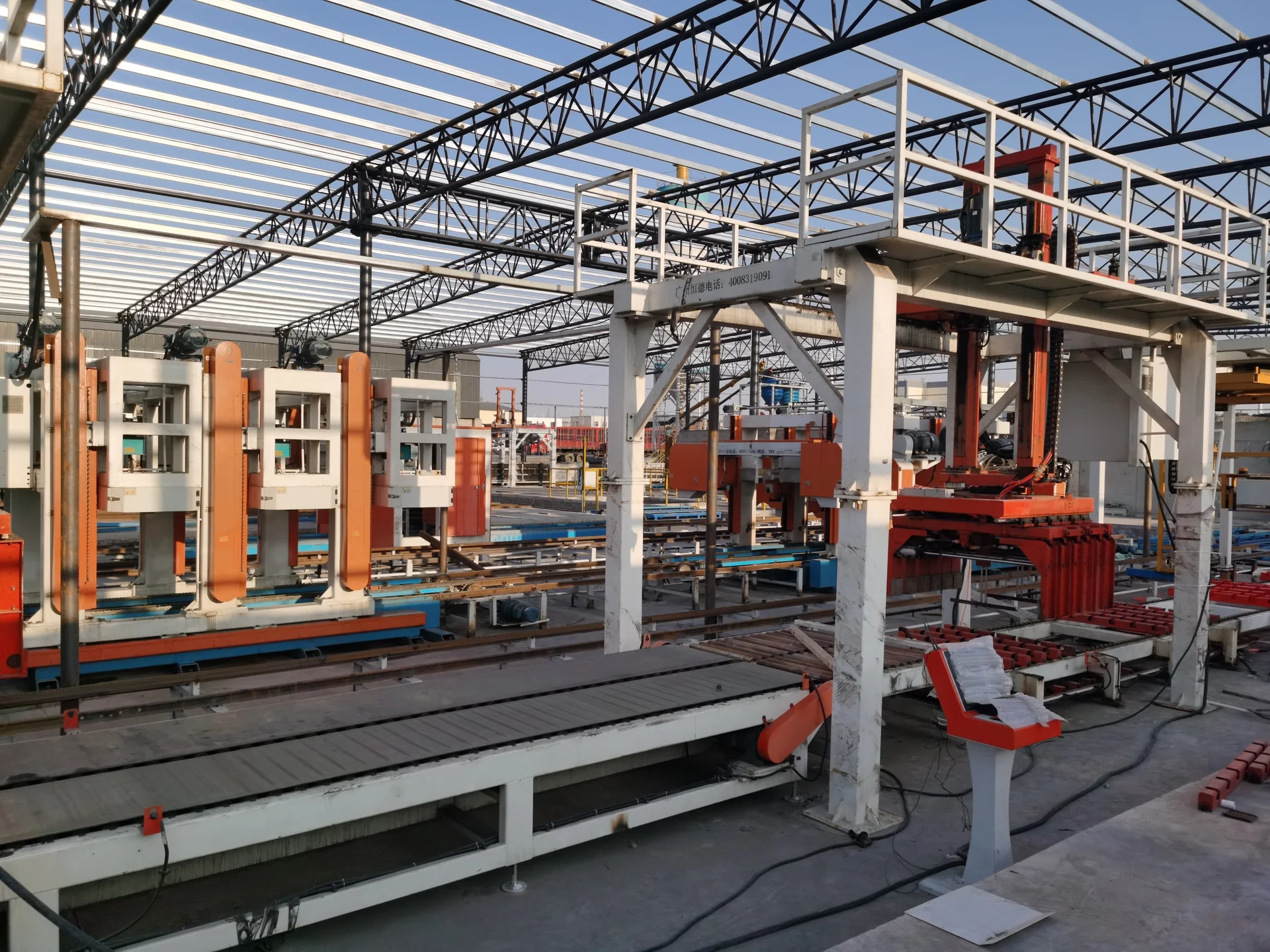
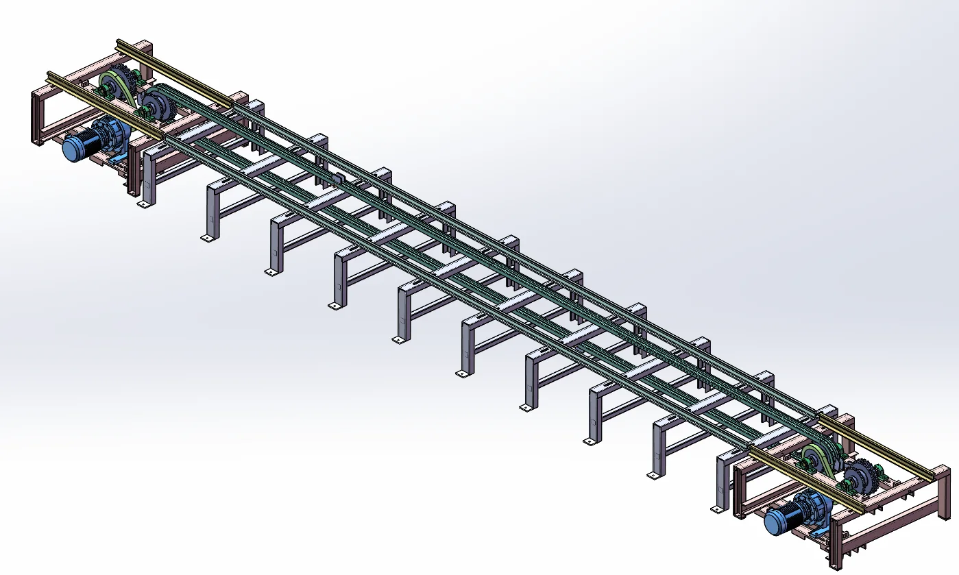
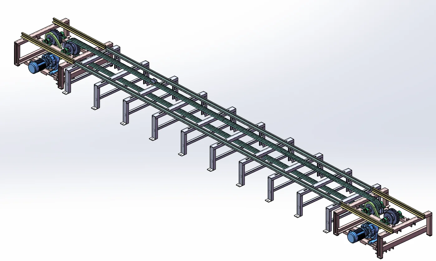
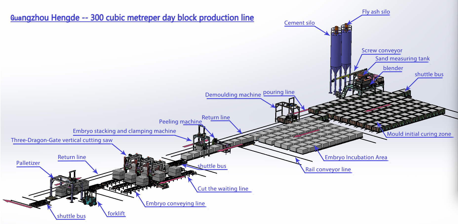
300 cubic metre per day CLC block production line engineering layoutOpen full-size layout
ENGINEERING LAYOUT300 m³/day CLC block production-line engineering layout. Final factory engineering follows the confirmed project conditions.

Production-line configuration at a glance

CAPACITY QUICK INFORMATION

300 m³/dayDesign capacity basis
37.5 m³/hourEngineering calculationNominal planning rate: published daily capacity ÷ one 8-hour production shift.
25Equipment items
Physical foaming · Non-autoclaved curingProcess
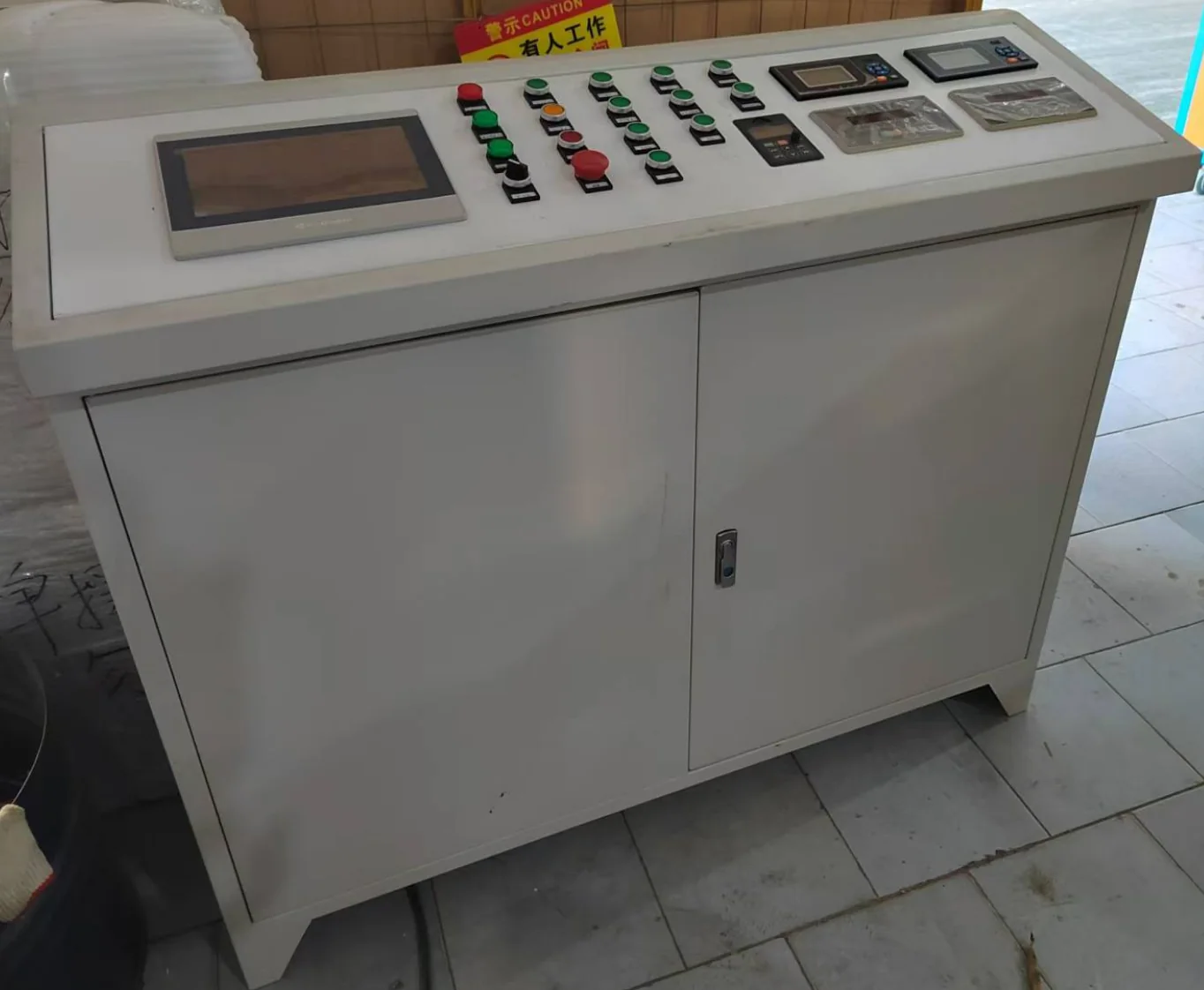
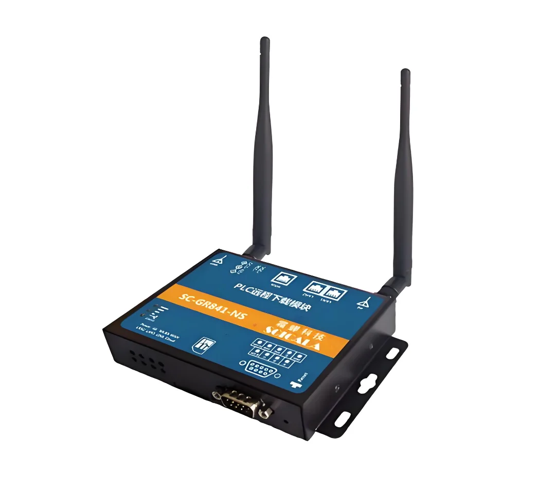
PLC control; handling varies by stationAutomation Level
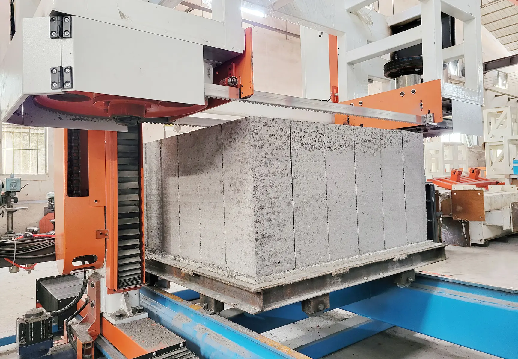
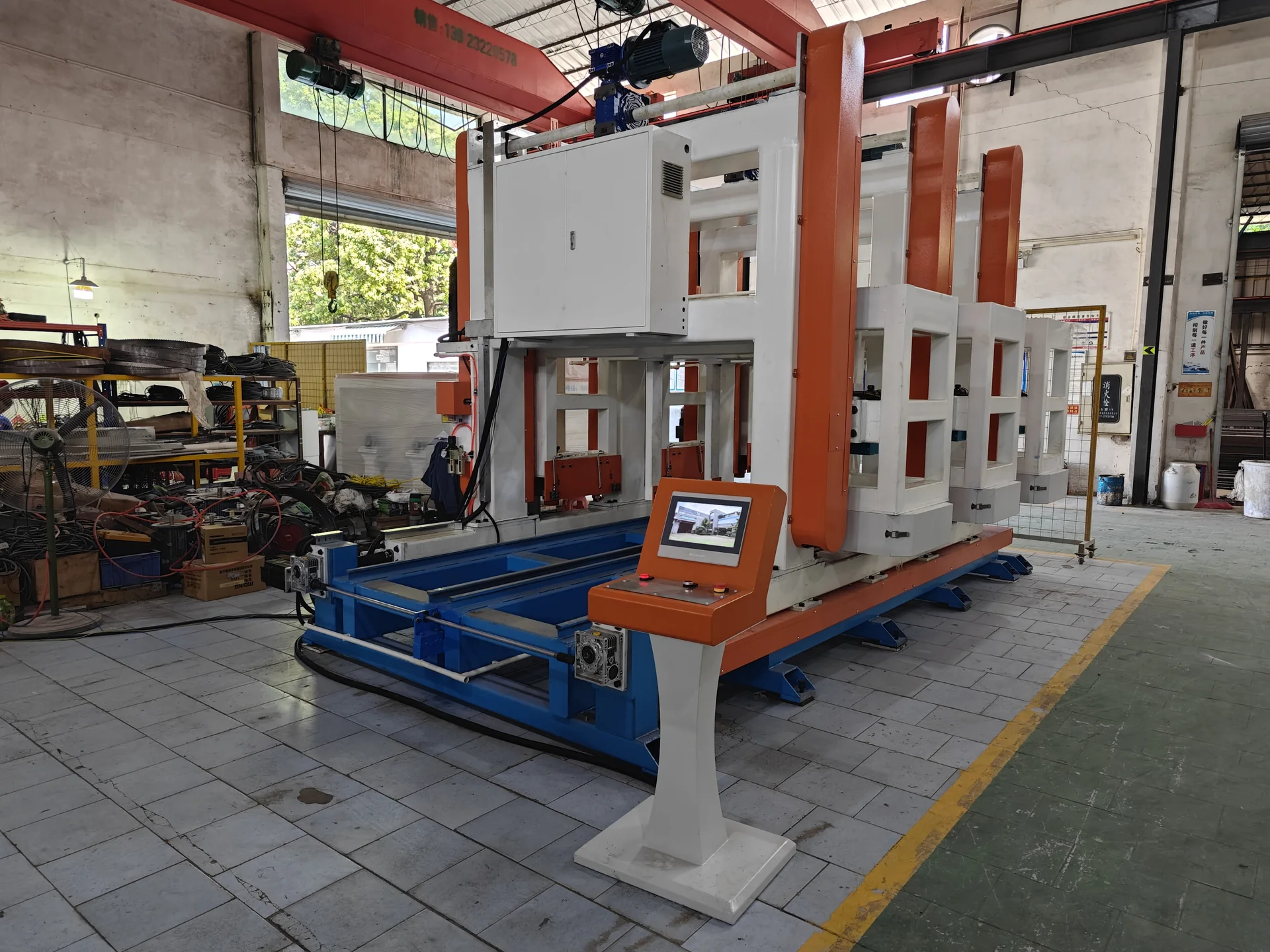
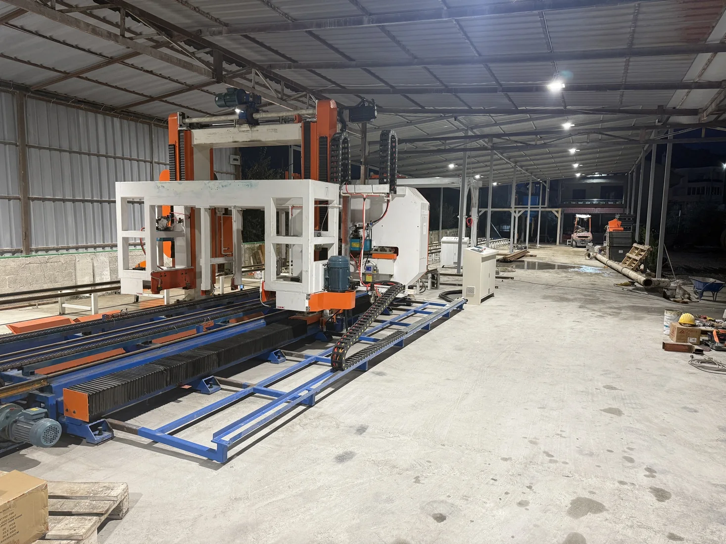
Peeling machine + Three-station rotary vertical sawCutting System
Engineering layout shown; site adaptation requiredFactory Layout

How the production line works

SIX-STEP PROCESS

  1. 01

    Prepare & meter

    Meter powder, aggregate and water to the batch formulation.

  2. 02

    Physical foaming & mixing

    Generate preformed foam and control its addition to the metered slurry for the target fresh density.

  3. 03

    Pour & mould

    Fill the mould configuration selected for the block product and production capacity.

  4. 04

    Non-autoclaved cure & demould

    Match the non-autoclaved curing time, mould count and demoulding condition to the product.

  5. 05

    Cut & finish

    Match billet condition, cutting sequence and transfer speed to the cutting system in this configuration.

  6. 06

    Transfer & stack

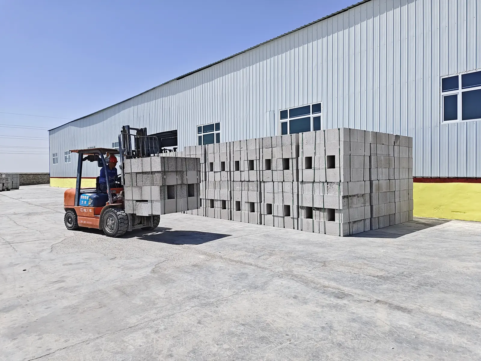
    Connect block transfer and stacking to the cutting cycle and finished-product storage area.

Complete equipment configuration

View models, quantities and listed power

COMPLETE EQUIPMENT CONFIGURATION

Review the equipment for each production stage. Select an equipment image to enlarge it, or open a linked equipment name for more detail.

The mould row below is not a complete production mould-fleet calculation. Final production mould quantity is confirmed during project engineering according to mould turnover and curing conditions.

300 m³/day CLC Block Production Line — equipment configuration
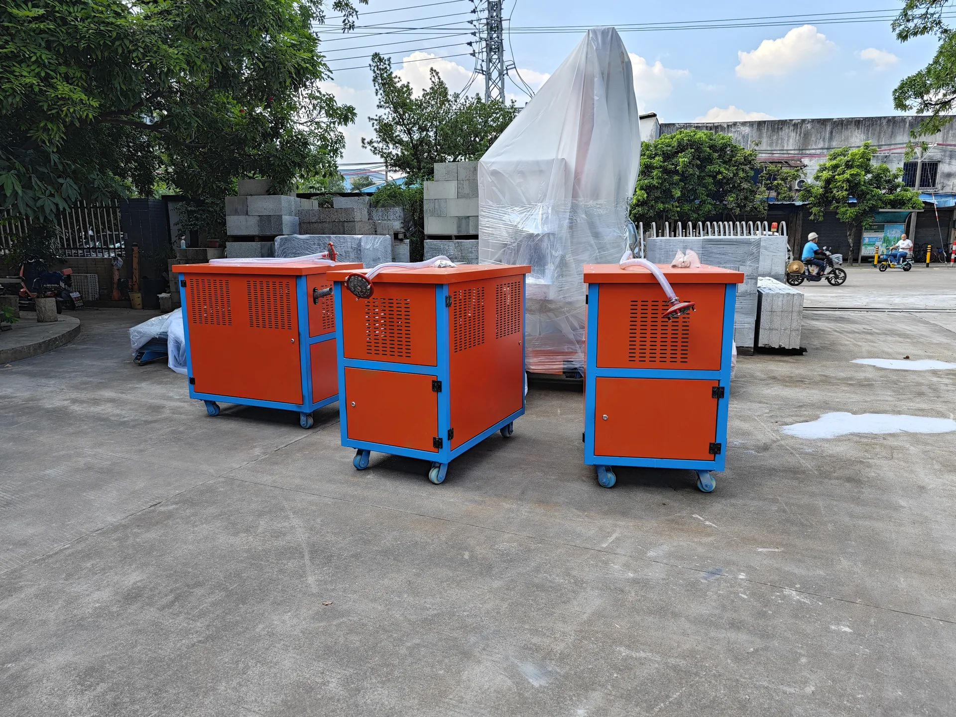
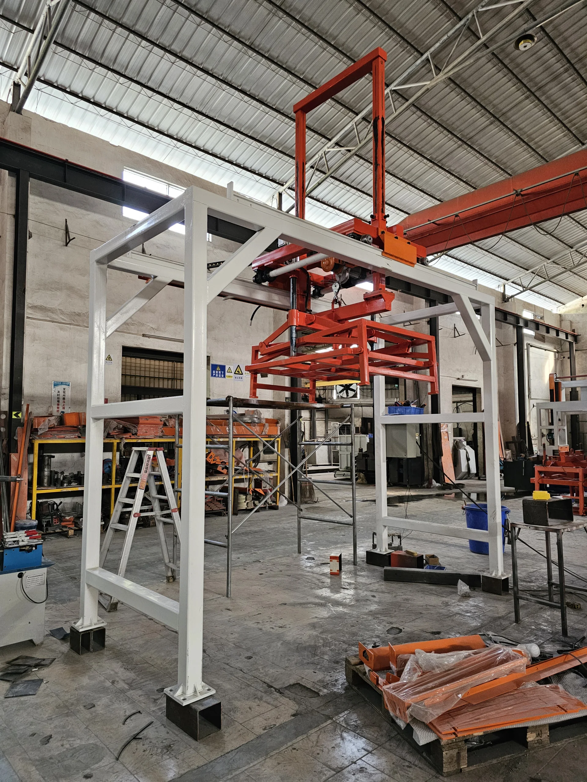
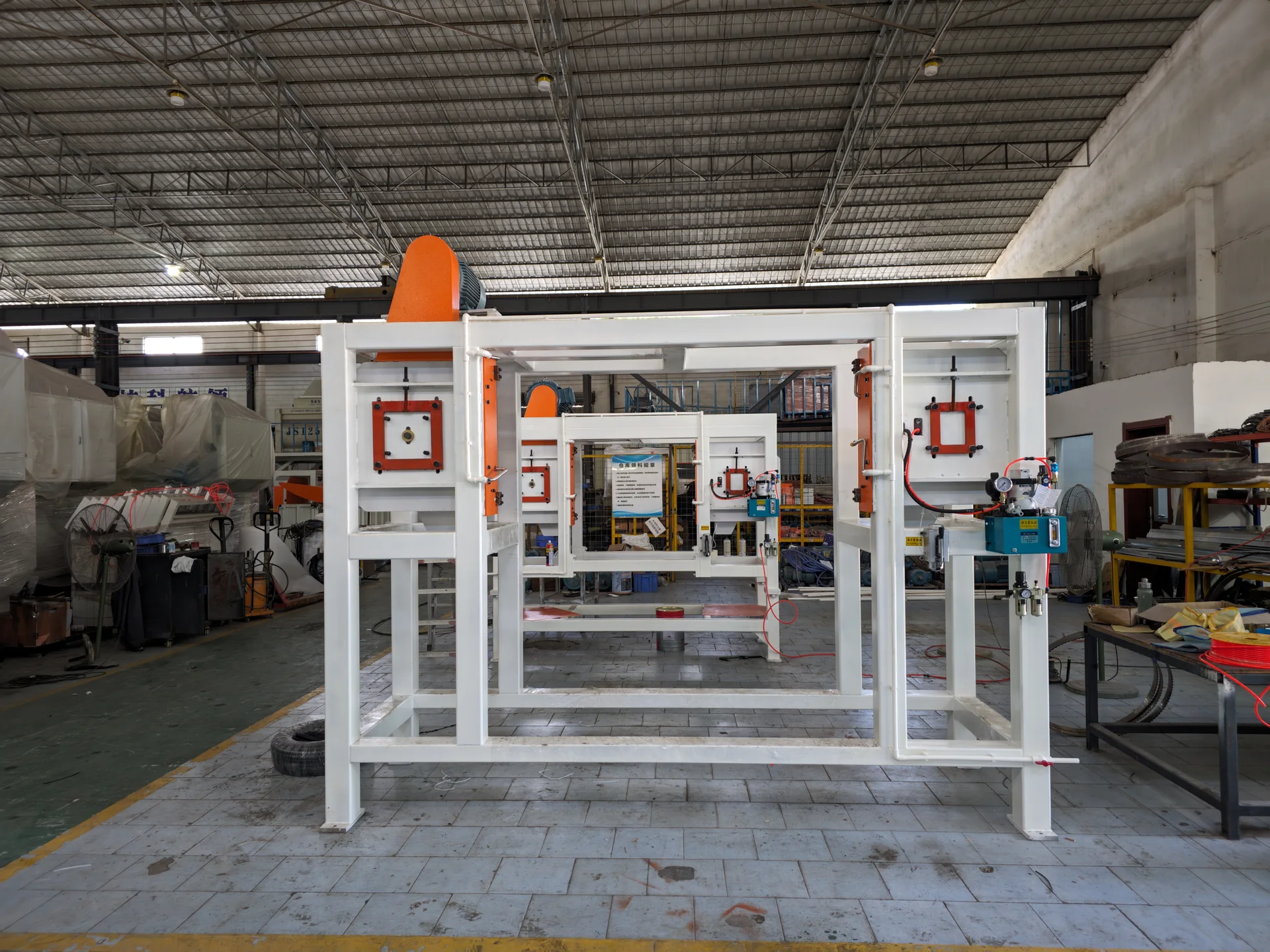
No.EquipmentStageModelDimensionsQty.Unit powerTotal power (kW)
Preparation & metering
1Preparation & meteringHDSL-0018640 × 350 × 1100111 kW11 kW
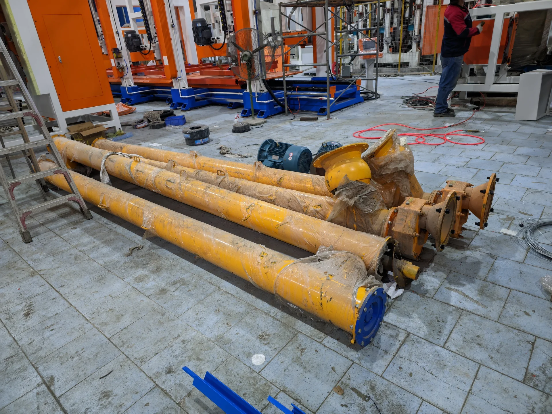
2Preparation & meteringHDKJ-00118000 × 800 × 80012.2 kW2.2 kW
3Preparation & meteringHDFL-001Ø1310 × H195010.55 kW0.55 kW
4Preparation & meteringHDFL-0011.2 m × 1.5 m × 1.4 m10.55 kW0.55 kW
5Preparation & meteringHDSL-001Ø1100 × H114010.55 kW0.55 kW
Physical foaming & mixing
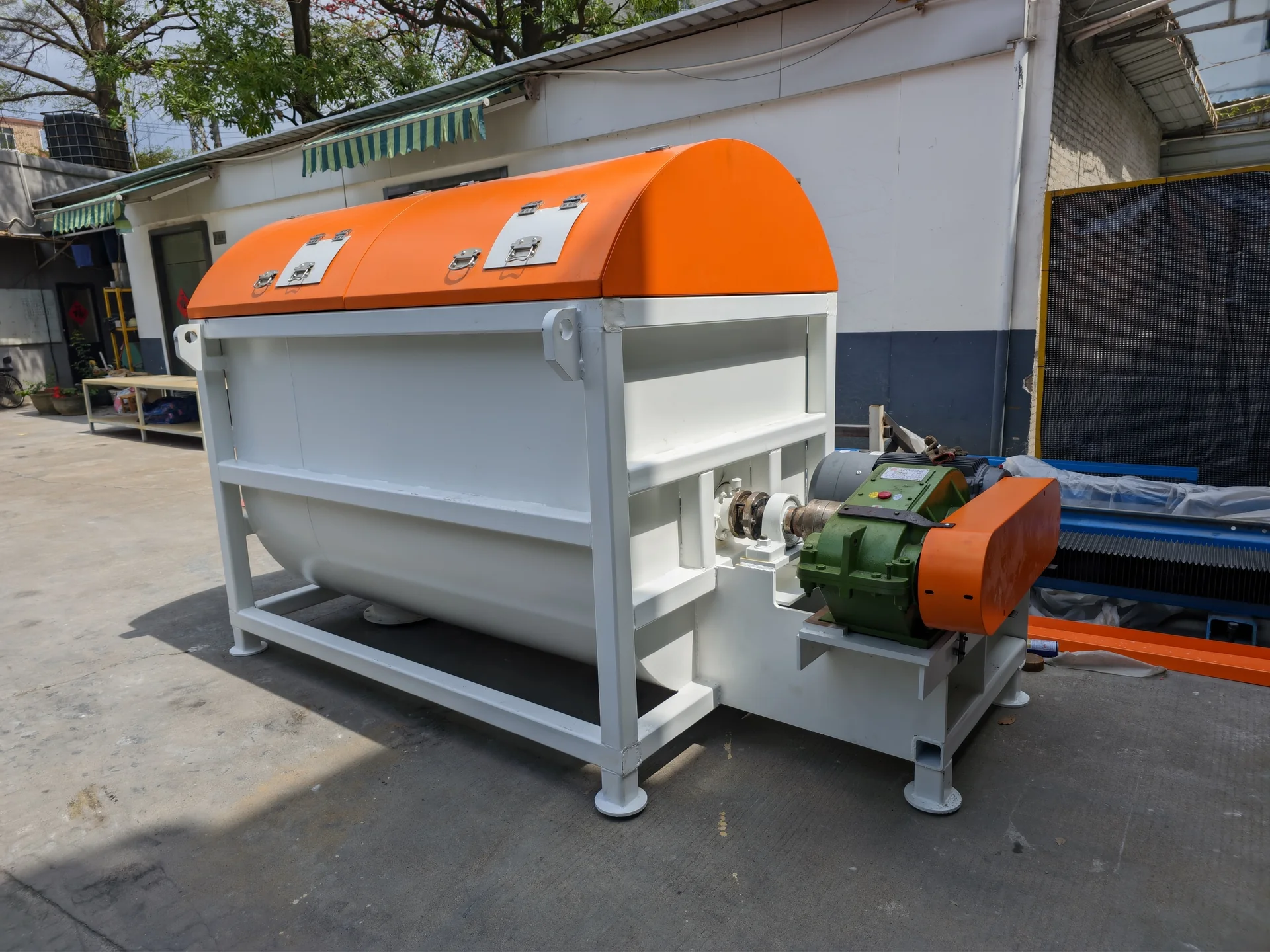
6Physical foaming & mixingHDKWF1-0011150 × 750 × 114017.5 kW7.5 kW
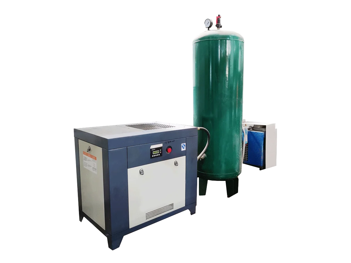
7Physical foaming & mixingHDKY-001L1500 × W500 × H2000 mm, air receiver0.8 m³*1115 kW15 kW
Preparation & metering
8Preparation & metering—5000 × 3500 × 15001——
Physical foaming & mixing
9Physical foaming & mixingEPSJB-021.9 m³122 kW22 kW
Preparation & metering
10
Minor-material metering system
Preparation & metering——1——
Handling & stacking
11Handling & stackingHDKHG-0014.9 m × 2.8 m × 4.2 m15 kW5 kW
Cutting & finishing
12Cutting & finishingHDOSD1-0013000*1000*2100 (including powered line)122 kW22 kW
Handling & stacking
13Handling & stackingHDTH-0052430 × 1330 × 390017.5 kW7.5 kW
Cutting & finishing
14Cutting & finishingHDSQ1-0039000 × 3300 × 3650 (high-precision rotary configuration)153.2 kW53.2 kW
Handling & stacking
15Handling & stackingHDTH-0064800 × 2600 × 380016.2 kW6.2 kW
Moulding, curing & circulation
16Moulding, curing & circulationHDBD2-0011800 × 1080 × 40063 kW18 kW
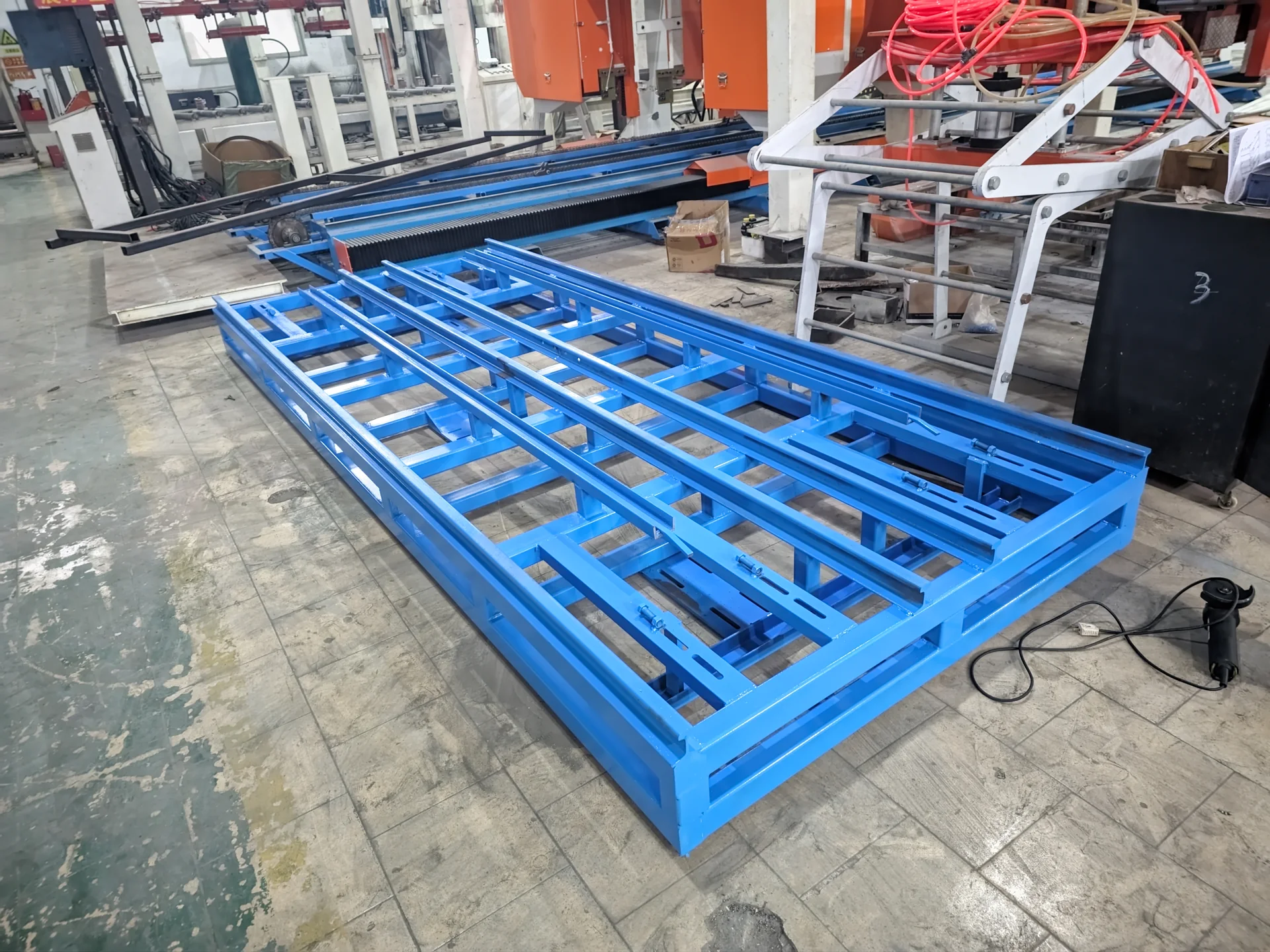
17Moulding, curing & circulationTM-00112 m × 1.1 m12.2 kW2.2 kW
18Moulding, curing & circulationHM-00112 m × 1.1 m12.2 kW2.2 kW
19Moulding, curing & circulationJZ-00112 m × 1.1 m12.2 kW2.2 kW
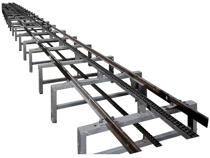
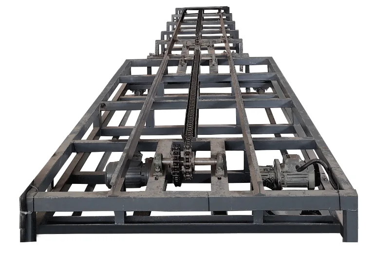
20Moulding, curing & circulationHDZD-0014 m × 1.1 m30.3 kW0.9 kW
21Moulding, curing & circulationHDZD-0024 m × 1.1 m30.3 kW0.9 kW
PLC, electrical & tooling
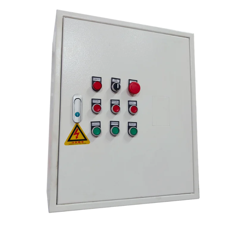
22PLC, electrical & toolingHDKZ1-0011300 × 1100 × 4001——
23PLC, electrical & toolingHDCBD1-001700 × 500 × 4001——
24PLC, electrical & tooling——1——
PLC, electrical & tooling
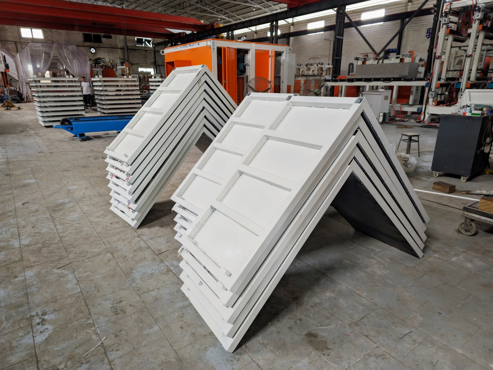
25Production equipmentHDCM1-0021220 × 1220 × 630 (complete set)1——

What changes in this 300 m³/day configuration

CAPACITY & EQUIPMENT CONFIGURATION

179.65 kW listed totalListed Power
Production mould fleet sized for mould volume, curing time and shift plan. The equipment table does not specify the total turnover fleet.Mould Quantity / Scope
Peeling machine × 1 · Three-station rotary vertical saw × 1Cutting Configuration
25 equipment entries; HENGDE plans their footprint, access and process connections around your siteFactory Requirements
HENGDE develops the 300 m³/day design basis into a shift, mould-turnover and curing plan for your productProduction Planning
Compare the equipment models, quantities, power and cutting system below to select the configuration for your factoryDifference vs Other Capacities

Compare 100, 200 and 300 m³/day on the same shift basis

View the existing capacity comparison and planning notes

CHOOSE YOUR FACTORY CONFIGURATION

Start with your block sales target and available casting hours. HENGDE matches mixing, cutting, mould circulation and handling as one production system. The comparison below uses the primary equipment configuration on each existing capacity page.

Physical-foaming CLC blocks · one 8-hour casting shift · design basis
Compare100 m³/dayPlan the mixing, mould circulation, curing, cutting and handling stages around your block and factory. Start with the equipment configuration and layout, then define the supply scope.300 m³/day
Nominal casting-planning rate12.5 m³/hour25 m³/hour37.5 m³/hour
Mixer model in this configurationHorizontal mixer · ADF-01No. 1 horizontal mixer · EPSJB-01No. 2 horizontal mixer · EPSJB-02
Cutting equipment in this configurationPeeling machine · HDOSD1-001; Single-station rotary vertical cutter · HDSHM1-01Peeling machine · HDOSD1-001; Two-station vertical cutter · HDSHM1-001Peeling machine · HDOSD1-001; Three-station rotary vertical saw · HDSQ1-003
Equipment entries242525

On a small screen, swipe the table horizontally to compare all three configurations.

These hourly figures are casting-planning calculations, not hourly saleable output. HENGDE sizes the mould fleet and curing area together with the cutting and handling cycle. A separate two-shift, 16-hour project proposal must be compared on its own basis.

Plan the whole factory footprint

Reserve separate areas for raw-material storage and feeding, mixing and casting, occupied moulds during curing, demoulding and cutting, finished-block storage and loading. The machine footprint alone is not the workshop requirement.

Send a dimensioned building sketch showing columns, clear height, doors and vehicle access. HENGDE turns it into a connected station layout with maintenance and lifting access.

Size utilities and operating roles

Use the selected equipment schedule to prepare the electrical load list. The sum of nameplate powers is not an electricity-consumption figure or a transformer selection.

Plan the water supply, drainage and any compressed-air connections with the station layout. Allocate responsibilities for material feeding, batching and casting, mould transfer, cutting, packing, quality checks and maintenance. Headcount follows the automation and shift plan, not the headline capacity alone.

Calculate mould circulation before ordering

Daily casting volume divided by usable fill volume gives casting cycles, not the number of moulds to buy. Mould count also depends on how long each mould stays occupied before it can be cleaned, prepared and filled again.

The equipment-list quantity “1” is not a complete turnover-fleet specification. HENGDE provides the production mould schedule with the agreed curing and shift plan.

Compare proposals by supply scope

Ask for a station-by-station schedule identifying supplied equipment, separate options and customer-prepared work. Check the total mould fleet, packing method, silos and platforms, civil foundations, electrical installation, transport and on-site services separately. An equipment total alone cannot show whether two proposals cover the same factory.

Read the equipment and factory-preparation guide · Factory layout planning · Request this configuration and scope schedule

From local materials to an operating factory

PROJECT DELIVERY / TURNKEY SUPPORT

HENGDE connects raw-material testing, factory planning, equipment manufacturing and site commissioning in one delivery plan. Our engineers develop the production route and machine interfaces, and our team prepares operators for production and maintenance. The proposal identifies the equipment, site preparation and services for your factory.

  1. 01

    Raw Material Testing

    Evaluate representative samples from the project location before selecting the final process.

  2. 02

    Formula Adjustment

    Adjust the formulation and material ratios against the test results and target product.

  3. 03

    Product & Process Selection

    Confirm product dimensions and the product-specific preparation, forming, curing and finishing process.

  4. 04

    Factory Layout Planning

    Coordinate land, buildings, storage, material flow, foundations and utilities.

  5. 05

    Production Line Customization

    Match capacity, automation, budget, moulds and process interfaces to the agreed factory scope.

  6. 06

    Equipment Manufacturing

    Prepare the agreed machines, tooling and controls against the approved configuration.

  7. 07

    Factory Acceptance

    Check applicable equipment and delivery scope before shipment.

  8. 08

    Packing & Shipping

    Coordinate packing, loading and destination requirements with the project shipping plan.

  9. 09

    Site Installation

    Install and connect the agreed equipment after site conditions are ready.

  10. 10

    Commissioning

    Check machine sequences and trial production with the selected materials.

  11. 11

    Operator Training

    Train operators in safe use, production sequence and routine maintenance.

  12. 12

    After-sales & Spare Parts

    Plan maintenance communication and spare-parts support for the installed equipment.

Planning a Lightweight Block Project?

PROJECT PLANNING

Tell us your target product, project location and planned output. The selected 300 m³/day configuration is included automatically.

Discuss Your Project

Discuss your project

Tell us about your project.

A few details give our team the right starting point for your production line proposal.

Delivery lead time: 40–50 working days.

WhatsApp HENGDE+86 159 8637 7799Opens WhatsApp. No message is sent automatically.
Related project or application300 m³/day CLC Block Production Line

WhatsApp is required. Email is recommended for receiving quotations and technical information.

Choose a calling code or enter a full international number. It may differ from your project country.
Add project details Optional — helps us prepare your configuration
Enter a positive amount, or leave blank. Pasting “200 m³ per day” also works.

Share only information you are permitted to provide. By submitting, you agree to the Privacy Policy. Fields marked * are required.